
Abstract
The small punch (SP) test is a widely accepted methodology for obtaining mechanical property information from limited material quantities. Much research has presented the creep, tensile and fracture responses of numerous materials gathered from small-scale testing approaches. This is of particular interest for alloy down selection of next-generation materials and in situ mechanical assessments. However, to truly understand the evolution of deformation of the miniature disc specimen, an accurate and detailed understanding of the progressive damage is necessary. This paper will utilise the SP test to assess the tensile properties of several Ti–6Al–4V materials across different temperature regimes. Fractographic investigations will establish the contrasting damage mechanisms and finite element modelling through DEFORM software is employed to characterise specimen deformation.
Introduction
The small punch (SP) test is a miniaturised mechanical test method that has previously been employed to evaluate neutron irradiation damage in nuclear reactor materials 1 and for remnant life assessment of power plant components extracted from operation. 2 The primary advantage of this approach relates to the small volume of test material required, such that the test technique has been employed across laboratories worldwide to obtain creep rupture lives and tensile fracture data on a wide variety of different material systems. However, recent research has utilised this approach for determining the mechanical properties of localised features such as weldments, heat-affected zones, coatings and interfaces.3–5 As such, engineers and designers are now looking to profit from the numerous benefits that SP testing can provide since it is often difficult to produce representative test specimens for conventional mechanical test approaches which reflect the true mechanical response of the component. 6
Since the early 1990s, Swansea University has invested significant effort into exploiting the promise of the SP test, where previous research has adopted the technique to characterise single crystal turbine blade alloys,7,8 next-generation titanium aluminide materials 9 and additive layer manufactured (ALM) components. 10 One such form of ALM that is readily receiving significant investment is electron beam melting (EBM). 11 In this process, an electron beam provides the power source to melt a metal powder that lies on a powder bed to then build up a component layer by layer, typically within a near-vacuum environment. This technique, like many other ALM processing routes, offers the potential to both decrease the cost and increase the speed of manufacture of complex geometry components. 12 One of the most significant cost saving factors is that less material is machined away as swarf, since the components are manufactured to near net shape, thus improving the buy-to-fly ratio. The reduced need for machining may also reduce the total manufacturing lead time. Furthermore, EBM may also allow the manufacture of complex component designs which would not be possible with other more conventional manufacturing techniques such as casting and forging.
In the present study, the small punch tensile (SPT) test technique will be employed to investigate the mechanical response of several differently processed variants of the titanium alloy Ti–6Al–4V over two temperature regimes and assess how the damage mechanism differs across them. This shall be achieved by performing a number of interrupted SPT tests to establish the modes of crack initiation, extensive post-test fractographic examinations to determine the fracture mode and finite element modelling (FEM) to assess the stress state evolution through the test.
Experimental methods
Materials
Ti–6Al–4V is widely used in the aerospace sector due to its favourable balance of mechanical properties. The alloy is alpha–beta processed and is routinely supplied in a number of different microstructural conditions, typically determined by the thermo-mechanical processing history of the material. In this study, research was undertaken on three Ti–6Al–4V variants, each of which were manufactured via a different processing route, specifically: (i) cast and hot isostatically pressed (HIP); (ii) forged disc and (iii) EBM.
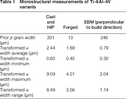
The cast and HIP material has a Widmanstätten grain morphology consisting of α and β phases with a colony size of parallel-orientated α phase lamellar of an approximate average size of 200 μm (Fig. 1a). The Ti–6Al–4V forged variant has an equiaxed bimodal structure with an approximate α volume fraction of 60% (Fig. 1b). The material for testing was extracted from the radial direction. The EBM material used in this research was built in a vertical orientation on an Arcam System configured with EBM Control 3.2 Service Pack 2 software. Before the EBM build, the pre-alloyed plasma atomised Ti–6Al–4V powder feedstock contained particles ranging from 45 to 100 μm in diameter. Further detail on the EBM process has previously been published in the literature.13–15 The microstructure presented in Fig. 1c displays the plane perpendicular to the build direction and represents the grain structure upon which the SP load is initially exerted. This microstructure displays a fine acicular-type grain morphology characterised by a columnar prior-β grain structure with epitaxial β ⟨100⟩ crystal growth parallel to the build direction (parallel and opposite to the principal direction of heat flow on cooling), as previously reported by the authors.
16
Analysis of the microstructural features was performed using the mean linear intercept method in ImageJ with grains measured both horizontally and vertically. A total of 300 measurements were made on each respective variant at random locations. Additional microstructural measurements characterising the typical grain sizes of the different Ti–6Al–4V variants are as given in Table 1.
Microstructure of a cast and HIP Ti–6Al–4V, b forged Ti–6Al–4V and c EBM Ti–6Al–4V (cross-section to the columnar grains developed parallel to the build direction). Each microstructure is representative of the face of contact on which the SP is loaded Microstructural measurements of Ti–6Al–4V variants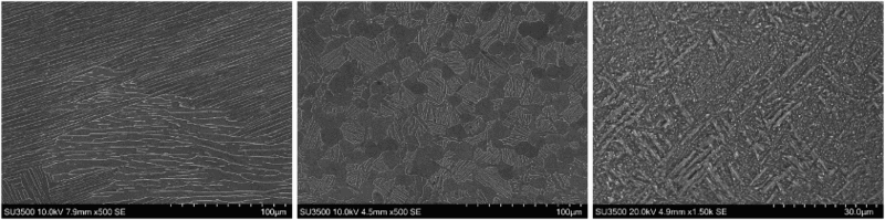
SP testing
A bespoke high temperature Nimonic-90 SP test jig has been designed to be accommodated within the load train of a universal, servo-actuated electric screw test frame in order to test miniature disc specimens at elevated temperatures. The test jig is comprised of an upper and lower die to clamp the miniature disc specimen in place. A hemispherical punch with a punch head diameter of 2.5 mm transfers the load applied normal to the flat surface of the miniature disc through a 4 mm receiving hole, the dimensions conforming to the European Code of Practice (EUCoP) for SP testing.
17
Each part of the testing jig is shrouded by a cylindrical support block which allows the jig assembly to be fastened to a servo-actuated electric screw uniaxial test machine. A schematic illustration of the test configuration is as shown in Fig. 2.
SP test configuration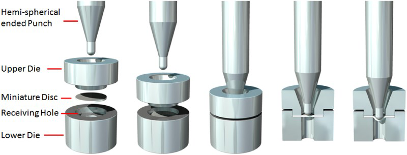
A variable load was applied to the miniature disc through the punch, under a range of constant displacement rates of 0.3, 0.6 and 1.2 mm min−1, based on recommendations from the EUCoP. 17 The displacement of the punch head was measured using two linear variable displacement transducers, one which is located in parallel to the axial load train and another that measures the residual deflection on the underside of the disc.
Testing was performed both at ambient room temperature and at an elevated temperature of 400°C, the upper operating temperature limit for several components made from the material. For these tests, a three-zone radiant furnace was employed to apply the desired temperature and this was constantly monitored throughout by two Type N thermocouples in direct contact with the lower surface of the miniature disc sample. The thermal gradient across the disc was maintained to ±1°C.
The SP specimens of EBM and forged Ti–6Al–4V were extracted from the threaded ends of conventional tensile specimens which had been turned down to a diameter of 9.5 mm. The cast and HIP specimens were extracted from a larger section of material using wire electrical discharge machining. In each case, the resulting cylinders were sectioned into slices approximately 800 μm in thickness before being ground down to the required thickness of 500 ± 5 μm using successively finer grades of silicon carbide abrasive paper, the final grade being 1200 grit in line with the recommendations of the EUCoP. 17 Disc thickness is then measured at five locations around the periphery and the centre of the specimen to ensure uniformity of thickness. Post testing, selected fractured specimens from each of the three materials were examined in detail using a scanning electron microscope.
Results and discussion
SP test results
Figure 3 presents the results from a series of SPT experiments on the forged Ti–6Al–4V variant tested at 20°C, each of which was subjected to a different displacement rate. The results show that the rate of displacement appears to have minimal effect in the early stages of deformation, with the peak load values falling within a range of 50 N. In each case, the previously reported typical stages of deformation usually found in a SPT test
18
are highly comparable. This includes the initial period of indentation and compression upon loading of the punch, followed by yield front propagation and membrane stretching. From this point onwards, the final stages of deformation are less uniform as each of the discs start to thin and crack in a more uncontrolled nature until final rupture occurs. Since minimal scatter is observed across the three tests despite the change in displacement rate, only the rate of 0.3 mm min−1 will be discussed further in this research. In accordance with the EUCoP,
17
in each test the final value of displacement is defined as a 20% drop in load once the maximum load is achieved.
Effect of displacement rate on forged Ti–6Al–4V tested at 20°C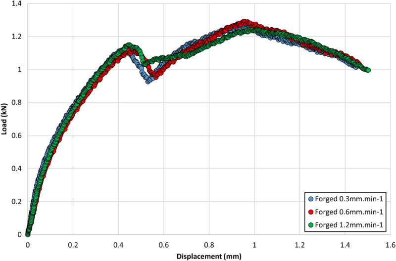
A number of SPT tests were then performed on the three Ti–6Al–4V variants across the two temperature regimes to directly compare their tensile responses. Figure 4 illustrates the relationship of load against displacement for the different variants and shows that, at room temperature, the cast and HIP and EBM materials behave in a very similar manner during the initial deformation modes up to the point where membrane stretching begins. The forged material appears to accumulate a higher proportion of load, indicating that this variant exhibits a stiffer response. This could be attributed to its reduced grain size (Table 1) in comparison to the other variants, following the relationship of the Hall–Petch theory.19,20 Unlike the EBM material, the cast and HIP and forged variants both achieve an ultimate load peak which is considerably higher than the first. Both materials also experience a larger level of displacement, thus further demonstrating the increased ductility in these materials compared to that processed by EBM, where cracking is considered to occur earlier in the deformation process. In comparison, at elevated temperature, the ordering of the three materials is similar, but here, the EBM variant offers a better response, relating to the improved ductility in the material at this temperature.
SP tensile response of cast and HIP, forged and EBM Ti–6Al–4V variants at ambient room temperature and 400°C, under a displacement rate of 0.3 mm min−1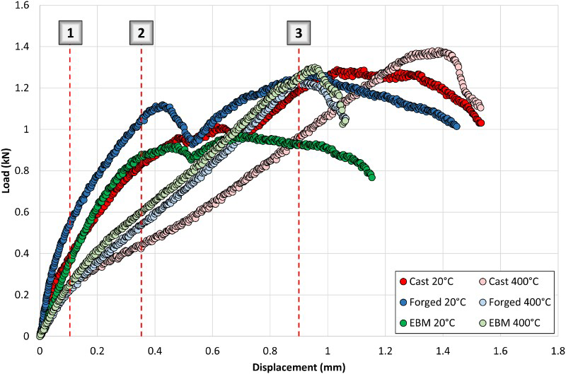
Post-test fractographic studies were undertaken to investigate the contrasting behaviours in each of the six SP test specimens. Figure 5 illustrates the topographic view of each of the six discs and a difference in the deformation modes can be seen. Figure 5c displays the fracture surface for the EBM material tested at 20°C and the disc appears to have failed in a predominantly brittle manner, as evidenced by the radial star-like cracking which can be seen to propagate towards the edges of the specimen. This behaviour directly correlates to previously published results on alternative materials that experience a distinctly brittle form of fracture.
21
In contrast, the extent of plastic deformation appears to be greater in the cast and HIP (Fig. 5a) and forged material (Fig. 5b) and the presence of radial cracking is less dominant. This conflicting behaviour is in accordance with the SPT results which demonstrate the greater displacement observed in the cast and HIP (approximately 1.53 mm) and forged material (approximately 1.45 mm) in comparison to the EBM material (1.15 mm) at 20°C. As the temperature is increased to 400°C, this discrepancy becomes less obvious. As given in Fig. 5d–f, the difference in the fracture behaviour across the three materials is minimal, with all discs experiencing a ductile form of failure (as evidenced by the concentric form of cracking), in comparison to the radial cracks that were present at 20°C. Further evidence of plastic deformation is provided by the slip lines that clearly emanate outward from the centre of each of the discs. This manner of failure compares favourably to SP fractography seen in several grades of steel
22
which also endure a typically ductile form of damage.
SP tensile fracture surfaces of a cast and HIP 20°C, b forged 20°C, c EBM 20°C, d cast and HIP 400°C, e forged 400°C and f EBM 400°C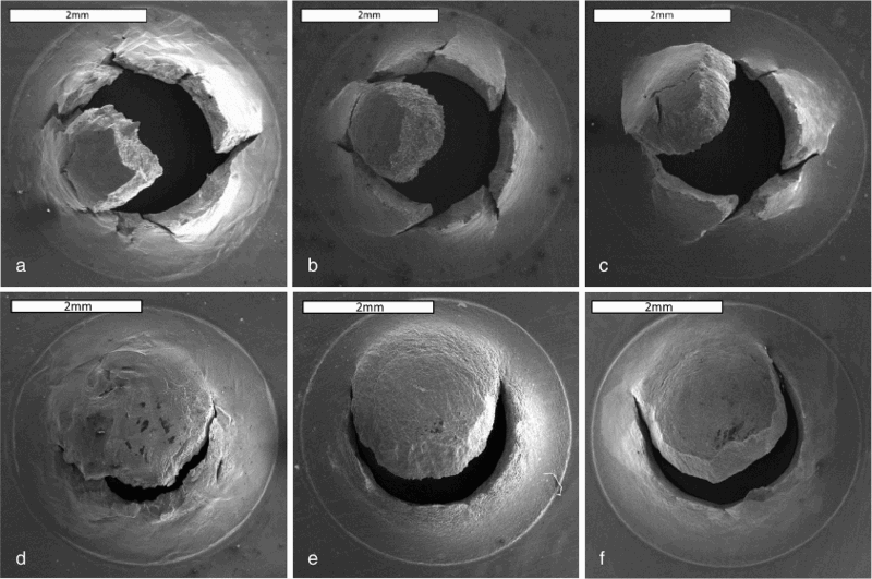
To address the differing behaviours across the two temperatures, an additional study was undertaken by interrupting a number of SPT tests after a fixed amount of displacement had been achieved. This series of tests were undertaken on the forged material so the results could be directly comparable. The tests were stopped after 0.1, 0.35 and 0.9 mm of displacement to capture the different components of the typical SPT curve, at both 20 and 400°C. The resulting fractography for these tests is displayed in Figs. 6 and 7.
SP tensile fracture surfaces for interrupted tests on forged Ti–6Al–4V material at 20°C after a 0.1 mm displacement, b 0.35 mm displacement and c 0.9 mm displacement SP tensile fracture surfaces for interrupted tests on forged Ti–6Al–4V material at 400°C after a 0.1 mm displacement, b 0.35 mm displacement and c 0.9 mm displacement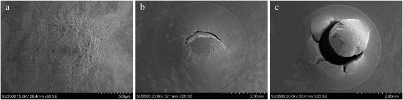
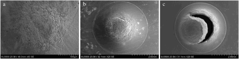
The fractography of the interrupted tests across the two temperature regimes indicate that cracking appears to initiate after a shorter period of displacement at 20°C compared to that seen at 400°C. This trend is captured in the load–displacement curves, where the tests at 20°C can be seen to experience a drop in load sooner than the comparative behaviour at 400°C, a phenomena thought to be linked to the onset of cracking in the material.
DEFORM finite element modelling
FEM using DEFORM was used to simulate this behaviour and to identify the stress evolution and specimen deformation across the two temperatures and how they differ. A numerical model of the deformation was developed using DEFORM standard code and due to the specimen geometry and the experimental set up detailed earlier, an axisymmetric model was adopted where the miniature disc specimen was firmly clamped along its entire contour. The outlay of the mesh employed and the axisymmetric model is shown in Fig. 8, where the specimen thickness was 0.5 mm, specimen diameter was 9.5 mm, the punch diameter was 2.5 mm and the lower and upper die receiving hole was 4 mm. The upper and lower die sets and the punch indenter were all modelled as rigid bodies insensitive to deformation in all degrees of freedom, as well as the horizontal or rotational movement of the punch being restricted. A model of 1000 CAX4 elements were used for the specimen, with the mesh further refined towards the contact area of the punch and specimen.
Axisymmetric model of the SPT experimental setup and the mesh employed using DEFORM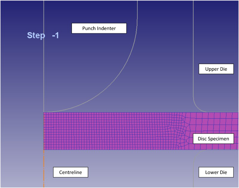
The material modelled was that of the Ti–6Al–4V forged variant, where isotropic material behaviour was assumed and flow stress data taken from the DEFORM metallic material database, where stress values are given over a range of applied strains, strain rates and temperatures, i.e. 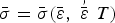 . The friction coefficient was set to a value of μ = 0.25 for the simulations since this value was previously reported to give more realistic results regarding disc deformation.23,24 A normalised Cockroft–Latham damage criterion value of 0.354 was input for the room temperature trials based on uniaxial test data,
25
whereas no criterion input was employed for the 400°C simulations.
. The friction coefficient was set to a value of μ = 0.25 for the simulations since this value was previously reported to give more realistic results regarding disc deformation.23,24 A normalised Cockroft–Latham damage criterion value of 0.354 was input for the room temperature trials based on uniaxial test data,
25
whereas no criterion input was employed for the 400°C simulations.
A comparison of the load–displacement behaviours from the experimental results and the DEFORM simulations at both 20 and 400°C is displayed in Fig. 9. In each case there is a relatively good agreement between the experimental and simulated results considering the material data used in the model is taken from the DEFORM material database and due to its availability, is not specific to the forged Ti–6Al–4V variant used in the SP experiments. The 400°C simulation plot is only shown for up to 1.5 mm of displacement as no damage criterion has been input and it is known the specimen would crack and rupture sometime before this magnitude of deformation. However, the input normalised Cockcroft and Latham damage criterion of 0.354 for the 20°C simulations offers a good agreement in terms of the first damage point on the load–displacement plot indicated by a load drop. This can be seen to occur at a load value of 1.30 kN and a displacement of 0.45 mm in the simulation, and 1.12 kN and 0.43 mm in the experimental trials. Although, there is no damage criterion in the 400°C simulations, the principle that the onset of cracking will take place sooner in the 20°C specimens is highlighted in the 0.35 mm interrupted fracture surfaces, as shown in Figs. 6b and 7b, where the damage is clearly more prominent in the 20°C specimen as previously highlighted.
Comparison of the load–displacement behaviour achieved through SP testing and DEFORM simulations at 20 and 400°C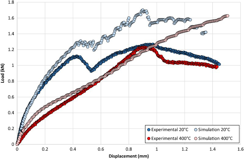
To complement the overall SP tensile responses from the simulations and experimental analysis, the model was interrupted after a series of displacement intervals (0.2, 0.5 and 1 mm) to help determine the complex and evolving stress state that occurs in a SP test. The evolution of maximum principal stress at both temperatures is shown in Figs. 10–12. The figures show that the evolving stress field at both 20 and 400°C follows the same trend, in that, upon initial loading there is a high compressive stress in the region of punch contact which results in localised yielding. The area of contact between the punch and specimen then increases as the punch displaces further through the specimen, and as a result, the point of maximum principal stress is found to propagate further from the centre of the specimen. This stress state evolution through the SP test is in agreement with that reported in the literature.26,27
FEA DEFORM simulation of the deformation of a forged Ti–6Al–4V SP disc after 0.2 mm displacement at a 20°C and b 400°C FEA DEFORM simulation of the deformation of a forged Ti–6Al–4V SP disc after 0.5 mm displacement at a 20°C and b 400°C FEA DEFORM simulation of the deformation of a forged Ti–6Al–4V SP disc after 1 mm displacement at a 20°C and b 400°C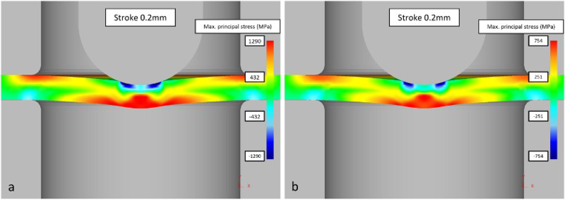
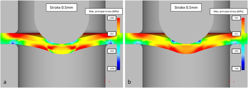
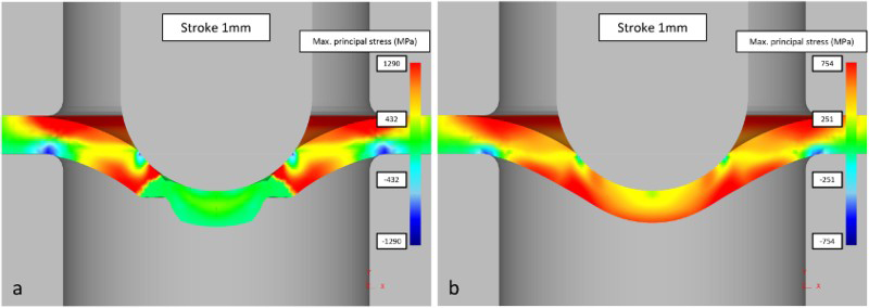
The expected difference is seen in terms of magnitude of maximum principal stress at the two temperatures, with higher values seen in the 20°C simulations, as is expected from the experimental results. Significantly, the damage criterion in the room temperature simulation results in the cracking occurring just off centre of the specimen, which conforms to the fracture surfaces of the room temperature specimens displayed in Fig. 6, with cracking approximately 0.6 mm from the centre in both cases. This therefore leads to a conclusion that a relationship exists between the failure criterion for uniaxial and SP tensile approaches, achieved by adopting the normalised Cockroft and Latham damage criterion value that was previously determined through uniaxial simulations. 25
Conclusions
The tensile properties and damage modes of forged, cast and HIP and EBM Ti–6Al–4V have been investigated through utilising the SP test technique. Results have shown that the SP tensile test can successfully characterise and rank the responses of the various materials and can distinguish the contrasting fracture modes that are observed across the two temperatures. The results are supported by DEFORM models which have shown real potential in modelling the evolving deformation through the miniature disc specimen under load. This was illustrated by comparable load–displacement curves at ambient room temperature which show good agreement between the results generated through experimental approaches and modelling simulations. The correlation showed that the normalised Cockroft and Latham damage criterion value, previously defined through conventional uniaxial methods, offered a suitable relationship across the two regimes.
Footnotes
Acknowledgements
The current research was funded under the EPSRC Rolls-Royce Strategic Partnership in Structural Metallic Systems for Gas Turbines (grants EP/H500383/1 and EP/H022309/1). The provision of materials and supporting information from Rolls-Royce plc is gratefully acknowledged by the authors, particularly the efforts of Christos Argyrakis, together with the assistance provided by the Swansea University AIM Facility, which was funded in part by the EPSRC (grant EP/M028267/1). Mechanical tests were performed at Swansea Materials Research and Testing Ltd (SMaRT). Requests for access to the underlying research data should be directed to the corresponding author and will be considered against commercial interests and data protection.