
Abstract
To understand the origin of white etching cracks (WECs), a systematic microstructural characterisation in the regions affected from the near-surface region down to the subsurface layers where WECs occur is necessary. As a starting point, we focus on the near-surface region of an axial thrust bearing, made of martensitic 100Cr6 steel, to study the influence of rolling contact loading on the microstructure and the resulting distributions of the major alloying elements C and Cr using atom probe tomography. We find that upon rolling contact loading the original plate-like martensitic structure evolves into a nanosized equiaxed grain structure with C segregation up to 5 at.-% at the grain boundaries. Cementite particles, located at grain boundaries and triple junctions, undergo spheroidisation. The originally homogeneously distributed Cr becomes enriched in spheroidised cementite particles. The microstructural changes give strong hints that rolling contact loading induces plastic deformation and an increased temperature on the near-surface region.
Keywords
Introduction
White etching cracks (WECs) have been identified as an essential premature wear failure mode in bearing components used in many industrial fields such as large gearboxes for wind power and automobile applications.1–6 The term ‘white etching’ stems from the homogenously white appearance of these regions in an optical micrograph after polishing and Nital etching. Although WECs have been extensively studied in the past years,3–6 due to the complexity of the operating conditions of bearing systems, which may involve contact mechanics, tribology and complex microstructures of the exposed materials, the detailed formation mechanisms of WECs are still unclear and remain a subject of intense research. 7 WECs are usually observed below the contact surface and in proximity to white etching areas (WEAs). 3 It is reported that WEAs consist of nanocrystalline carbide-free grains with sizes varying from 10 to 300 nm.5,8–11 However, it is still not known whether WEA is a symptom or a cause of cracking.7,12–14 Recently, Bhadeshia and Solano-Alvarez 15 made a thorough assessment of possible causes for WEC formation. They proposed that WEAs are likely preceded by cracks and result from the localisation of collision-induced plastic deformation between crack faces. Influencing factors such as the dissolution and the thermal stability of proeutectoid carbides were also discussed. 15
So far, most investigations were conducted using optical microscopy (OM),3,6 transmission electron microscopy (TEM)3,16,17 and scanning electron microscopy (SEM).3,5,16,17 The nanoscale nature of the underlying mechanisms requires to use smaller scale probing methods though. Here, we use atom probe tomography (APT) to reveal the microstructural features and their evolution in a bearing washer upon rolling contact loading. APT can provide both chemical identity and 3D locations of atoms in the sample. The method is thus an excellent tool to study phenomena involving solute distribution, segregation, dissolution/formation of nanoscale particles at the atomic scale.18–27 For example, the APT characterisation of cold-drawn pearlitic steel wires has provided remarkable insights into mechanisms of deformation-driven dissolution of cementite 18 and formation of nanocrystalline grains. 25 So far, very limited works have been done on martensitic bearing steels using APT. 11
WECs are mainly observed within the first 1 mm below the contact surface. 3 This zone corresponds to the region of maximum shear stress predicted by the elastic Hertzian contact theory. 28 On the other hand, since the stress state predicted by Hertzian theory varies from the surface into the depth of the contact bodies, it would be interesting to investigate whether the microstructure responds to the variation of the stress state and exhibits different features at different depth, ranging from the surface down to the highly sheared regions where WEC occurs. In the present work, we focus on the near-surface region of a martensitic 100Cr6 axial thrust bearing of type 81212 6 to study the influence of rolling contact loading on the microstructure and the distributions of the major alloying elements C and Cr. The investigations were performed in both the bearing prior to and after rolling contact loading. It was found that the rolling contact loading not only modifies the microstructure but also causes growth and spheroidisation of cementite on the bearing near-surface region.
Experimental methods
The material studied in this work was taken from the washer surface of a thrust bearing (type 81212). The initial bearing material was a through hardened martensitic 100Cr6 steel subjected to low temperature tempering at roughly 150°C. WECs were generated by rolling contact performed on a FE8 test rig
6
under the conditions given in Table 1. During the rolling test, the bearings were operated under mixed friction conditions with a lubricant (mineral oil ISO VG 100) film thickness of about 0.59 μm. The test was ended after a runtime of 200 h with WECs in the circumferential section of an exposed bearing washer in the etched condition. a SEM image in secondary electron (SE) mode showing cracks located beneath the contact surface. Magnification of the selected region in a is displayed in b (optical image) and c (SEM image in SE mode) Test conditions for creating artificial rolling contact damage rolling cycles when the beginning of pitting damage on the raceway was detected by a sensor. WECs were detected by OM and SEM (see Fig. 1) on cross-sections of the bearing perpendicular to the race track in the zone ranging from 100 to 300 µm below the contact surface.
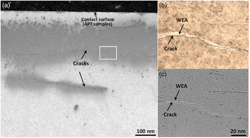
APT investigations were performed using a local electrode atom probe (LEAP 3000X HR ™, Cameca Instruments) in voltage mode at 70 K, using a pulse fraction of 15%, a pulse repetition rate of 200 kHz and a detection rate of 0.01 atoms per pulse. Samples for APT were prepared using a dual-beam focussed ion beam (FIB)/SEM instrument (FEI Helios NanoLab 600TM). The length axes of the needle-shaped APT specimens were oriented perpendicular to the contact surface with the specimen apex pointing towards the surface. About 200 nm of sample length was removed during FIB-based specimen preparation. This means that the APT measurements cover regions starting from approximately 200 nm below the contact surface, that is, the present investigations are focussed on the near-surface region. Figure 1 shows the investigated region where the APT samples were extracted with respect to the contact surface and the position of the WEA/WECs. Regarding the details concerning APT data analysis, identification of elements and 3-D reconstruction readers are referred to our previous works.18,29
Results and discussion
Figure 2a displays 3D atom maps of the elements C and Cr from the initial bearing material prior to mechanical loading. The lamellar-like structure consists of alternating C-depleted and C-enriched regions spaced about 20 nm apart (see Fig. 2a top). Borrow et al. 30 describe the microstructure of tempered martensitic 100Cr6 bearing steel based on TEM measurements as plate-like martensite with elongated and aligned carbides within the martensitic plates. The fine C-rich features observed in the current APT measurements represent these aligned carbides within a tempered martensite plate. Figure 2a bottom shows the atom map of C with green-coloured isoconcentration surfaces plotted at 7 at.-% C. Two regions of interest (ROIs) are selected for quantitative analyses of C and Cr in the lamellar structure (ROI I) and in the large C-rich particle (ROI II). The yellow arrows (Fig. 2a bottom) mark the directions along which 1D concentration profiles are plotted, as seen in Fig. 2b for ROI I and Fig. 2c for ROI II. The peak values for C concentration in Fig. 2b lie in the range from 5 to 15 at.-%. These values are below the stoichiometric value of 25 at.-% C for cementite, but above the value typically observed for grain boundary segregation.23,29,31,32 Therefore, an important assignment lies here in the capability to identify C atoms as being either in a segregated or in a precipitated state.
Recently, in as-quenched low-C steels it was observed that C atoms are partially dissolved in solid solution and partially segregated at defects such as dislocations and various martensitic boundaries (up to 7 at.-% C).31–33 Even cementite precipitation occurs in as-quenched low-C martensitic steels
34
due to a high martensite start temperature APT analysis of the initial bearing material prior to mechanical loading. a 3D atom maps of C (red) and Cr (pink). The isoconcentration surfaces for 7 at.-% C are shown in green. Two regions of interest (ROIs) – ROI I and ROI II – are selected for further concentration analyses of C and Cr. 1D concentration profiles of C and Cr along the yellow arrow directions marked in a are shown in b for ROI I and c for ROI II. Neither enrichment of Cr at the C-enriched layers (ROI I) nor its partitioning in the cementite (ROI II) is detected (about 400°C), which induces autotempering in martensitic regions that form at elevated temperatures. In the present case of 100Cr6 with very high C concentration (0.98 wt-%),
  (about 100°C) is probably low enough to suppress significant autotempering of martensite; however, the quenched and low temperature-tempered (about 150°C) martensite is strongly supersaturated with C, which may yield a high driving force for precipitation.
7
Moreover, the local magnification effect – a well-known atom probe artefact that leads to overlaps of ion trajectories35,36 – leads to the fact that Fe atoms stemming from the surrounding Fe-rich matrix can be incorrectly detected within the first 1–2 nm of C-rich regions. This leads to an underestimation of the C concentration in the first 1–2 nm vicinity of the C-rich regions. In case of ROI I in Fig. 2a and b, the C concentration is affected by this artefact due to the small size of the C-enriched regions. Due to this artefact, the nature of the C-rich thin films enclosed by isoconcentration surfaces in ROI I cannot be definitely identified. This means that these regions might be thin cementite films but also the presence of transition carbides37–40 cannot be excluded.
(about 100°C) is probably low enough to suppress significant autotempering of martensite; however, the quenched and low temperature-tempered (about 150°C) martensite is strongly supersaturated with C, which may yield a high driving force for precipitation.
7
Moreover, the local magnification effect – a well-known atom probe artefact that leads to overlaps of ion trajectories35,36 – leads to the fact that Fe atoms stemming from the surrounding Fe-rich matrix can be incorrectly detected within the first 1–2 nm of C-rich regions. This leads to an underestimation of the C concentration in the first 1–2 nm vicinity of the C-rich regions. In case of ROI I in Fig. 2a and b, the C concentration is affected by this artefact due to the small size of the C-enriched regions. Due to this artefact, the nature of the C-rich thin films enclosed by isoconcentration surfaces in ROI I cannot be definitely identified. This means that these regions might be thin cementite films but also the presence of transition carbides37–40 cannot be excluded.
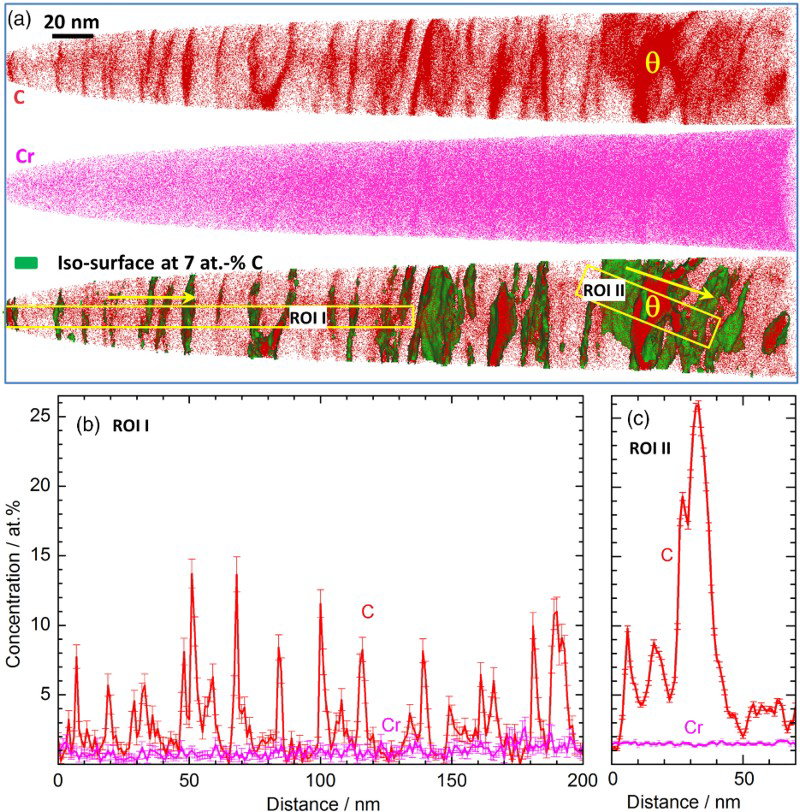
In case of the large C-rich particle in ROI II the core is not concerned by the local magnification effect. The measured concentration of 25 at.-% C in the core of this particle clearly identifies it as cementite. In contrast to C which is distributed inhomogeneously throughout the sample, Cr shows, neither in the C-rich thin films in ROI I nor in the large cementite particle in ROI II (see Cr atom map in Fig. 2a middle), any distinct segregation/enrichment. The corresponding concentration profiles of Cr do not show any concentration peaks (see pink lines in Fig. 2b and c).
Figure 3a and b shows two examples of APT analysis from the near-surface region of the bearing washer after exposure to APT analyses on the exposed bearing steel ( 1D concentration profiles of C (top) and Cr (bottom) mapped perpendicular to the boundary plane for all grain boundaries marked in Fig. 3 Proximity histograms of C (red, top), Cr (pink, bottom) and Si (grey, bottom) obtained from multiple martensite matrix/cementite interfaces shown in Fig. 3. Thin lines represent the average concentration values over  rolling contact cycles at 100°C. Distinctly different from the bearing prior to loading where a plate-like martensitic structure with elongated and aligned carbides inside the plate prevails, the deformed material exhibits a nanosized equiaxed grain structure with grain sizes varying from 20 to 50 nm. In addition, cementite (as will be identified below) particles undergo spheroidisation and are located at grain boundaries and triple junctions. In the coarse cementite particles, distinct enrichment of Cr (see Cr atom map in Fig. 3b) is observed. A similar nanosized grain structure has also been reported by Kang et al.
11
in 100CrMo7 bearing steel, where no spheroidised cementite particles at grain boundaries were observed. This difference suggests that in the current sample a strong annealing effect due to an increased temperature on the near-surface region may exist. It is noted that the APT investigations in
11
were conducted on the WEA at about 200 μm below the contact surface, whereas the present study is focussed on the near-surface region (about 200 nm below the contact surface).
rolling contact cycles at 100°C. Distinctly different from the bearing prior to loading where a plate-like martensitic structure with elongated and aligned carbides inside the plate prevails, the deformed material exhibits a nanosized equiaxed grain structure with grain sizes varying from 20 to 50 nm. In addition, cementite (as will be identified below) particles undergo spheroidisation and are located at grain boundaries and triple junctions. In the coarse cementite particles, distinct enrichment of Cr (see Cr atom map in Fig. 3b) is observed. A similar nanosized grain structure has also been reported by Kang et al.
11
in 100CrMo7 bearing steel, where no spheroidised cementite particles at grain boundaries were observed. This difference suggests that in the current sample a strong annealing effect due to an increased temperature on the near-surface region may exist. It is noted that the APT investigations in
11
were conducted on the WEA at about 200 μm below the contact surface, whereas the present study is focussed on the near-surface region (about 200 nm below the contact surface).
 rolling cycles under a contact stress of 2.1 GPa at 100°C). a and b display two examples of 3D C (red) and Cr (pink) atom maps of the exposed bearing steel. Both measurements show the formation of a nano-scaled grain structure with C segregation at grain boundaries. The isoconcentration surfaces for 7 at.-% C are shown in green. Numbers 1–6 mark the grain boundaries at which the distributions of C and Cr are analysed and presented in Fig. 4.
  and
and  mark smaller,
  to
to  mark larger cementite particles, respectively. The detailed chemical analysis of these precipitates is given in Fig. 5
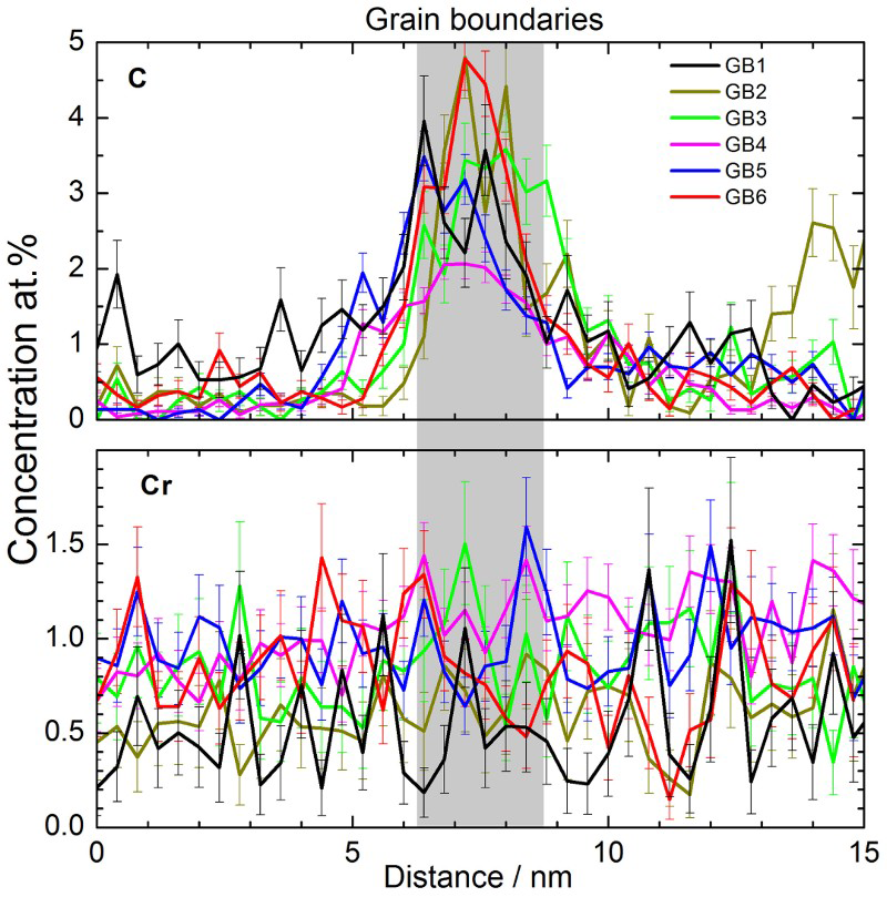
 and
and  and thick lines over
  ,
,  and
and 
For selected grain boundaries and cementite particles (Fig. 3), a detailed analysis of the distributions of C and Cr was conducted (Figs. 4 and 5). Figure 4 shows 1D concentration profiles of C (top) and Cr (bottom) across six grain boundaries. C is segregated at the grain boundaries with concentration values varying from 2 to nearly 5 at.-%, whereas Cr is not enriched at any of the six boundaries. The variation of the peak C concentration between different grain boundaries can be explained by the high dependence of grain boundary segregation on the crystallographic grain boundary parameters such as the grain misorientation angle, axis and the grain boundary plane orientation. 23 Also, the presence of carbides in proximity to the grain boundary might have an effect, since under certain thermodynamic conditions the presence of C in cementite is energetically favoured in comparison to its presence at grain boundaries. 26
The elemental distribution profiles from within the core of the precipitates, across their interfaces, into the bulk of the martensitic matrix are quantified using proximity histograms (proxigram). 41 Figure 5 shows the proxigrams of C, Cr and Si averaged over multiple interfaces. The thin and thick lines represent data averaged over interfaces marked in Fig. 3a and b, respectively. In the middle of the carbides, the concentration of C reaches 25 at.-%, which corresponds to the stoichiometric composition of C in cementite. Cr is enriched in the small carbides with a concentration of 1.3 at.-% and nearly 2 at.-% in the large cementite particles. Si is depleted in the cementite, which is consistent with the result predicted by Themo-Calc, namely, that Si is nearly undissolvable in the cementite. 42
When comparing the initial bearing material with the bearing after rolling contact loading significant chemical and microstructural differences become apparent. First, the plate-like martensitic structure in the initial material has been replaced by a nanosized equiaxed grain structure with grain sizes varying from 20 to 50 nm. Second, during rolling contact loading the carbides have undergone spheroidisation so that they now can be well identified as cementite by means of APT. Third, Cr, which used to be homogeneously distributed across the martensitic matrix, the carbides and all interfaces for all samples investigated in the initial bearing material, have become enriched in the carbides during deformation. These microstructure features are very similar to those observed in heat-treated cold-drawn pearlitic steel wires.23,26,29 In the latter case, a nanoscale cellular/subgrain structure forms upon severe plastic deformation which is accompanied by the deformation-driven dissolution of cementite.18,25 The cellular substructure coarsens slightly upon subsequent heat treatment. 26 The formation of the equiaxed nanoscale grain structure observed in the bearing steel suggests that plastic deformation occurs on the near-surface region during rolling contact loading. Although only elastic deformation is usually assumed to be involved on the contact surface and the near-surface region in the presence of a lubricant film between the roller and the washer of a bearing system, accumulative plastic deformation can be introduced by a rough surface and sufficiently high local stress in rolling contact during the operation of bearings. Spheroidisation of the elongated/aligned cementite and distinct enrichment of Cr in the core of cementite particle (see Cr atom maps in Fig. 3) in the deformed sample indicate that local temperatures during rolling contact loading in bearings may well be above 100°C.
Conclusions
The influence of cyclic rolling contact loading on the microstructure of a martensitic 100Cr6 steel bearing washer was studied using APT placing focus on the near-surface region. The microstructure in the as-received state is characterised by a plate-like martensitic structure consisting of alternating C-depleted and C-enriched regions spaced about 20 nm apart. Cr is found to be homogeneously distributed throughout the whole detected volume including the martensite matrix and the carbides. Rolling contact loading under 2100 MPa at 100°C for 200 h changes the plate-like martensitic structure into an equiaxed nanosized grain structure with C segregated at grain boundaries. Cementite spheroidisation is observed during rolling contact load and the resulting large precipitates are located at grain boundaries and triple junctions. Cr is observed to be enriched in the core of spheroidised cementite, indicating that the local temperature during cyclic rolling contact test may well exceed the desired value of 100°C during the experiment. We suggest that the formation of the nanosized grain structure with spheroidisation of cementite in the damaged state result from a combined effect of accumulative plastic deformation and an annealing process enabled by a locally increased temperature due to surface deformation and friction.
Footnotes
Acknowledgements
The authors thank Mr A. Sturm from the Max-Planck Institut für Eisenforschung for FIB-based specimen preparations. We would also like to thank Mr M. Ploß and Mr G. Burghardt from Institute for Machine Elements and Machine Design, RWTH Aachen University for carrying out the rolling contact fatigue tests.
References
 transition in 100Cr6 and its effect on mechanical properties