
Abstract
Introduction
The aim of this paper is to describe the results obtained of a static test of flexo compression in polyaxial transpedicular conical cylindrical screws; which we have used for more than 20 years; in posteriors thoracolumbar spine fixings based on the ASTM F 1717–04 standard. This trial was made at the National Institute of Industrial Technology at its Center for Research and Development in Mechanical in Buenos Aires, Argentina.
Material and Methods
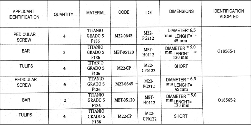
Two spinal fixation systems were evaluated, both composed by transpedicular conical soul and cylindrical thread screws, bars and tulips. In Table 1 the information provided by the manufacturer of the screws and identification adopted in the test for each sample is presented.
Sample identification
A universal testing machine Tinius Olsen H50-KT was used for the study. The proposed paragraph 8.1.1 of ASTM F1717–04 procedure was followed. The assembly of the samples was performed using the steps proposed by us, the tulips were set at the distance established by the Standard and the terminal screw of them was set by applying a torque of 10 Nm. The assays were performed at a speed of 10 mm / min and were interrupted when the load drop was observed in the instant graphic verifying in this way the loss of poliaxiality. The test setup used and the location of the devices during the test are shown in Fig. 1.
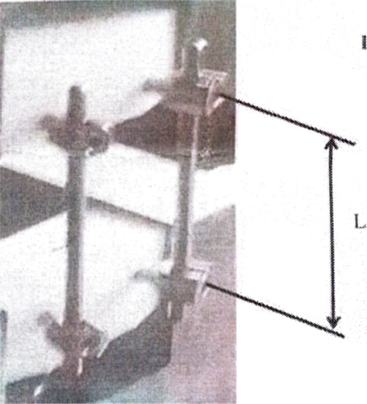
Test configuration used.
The active length of longitudinal component (L) was revealed (see Fig. 1). From this value the corresponding displacement of 2% of the permanent deformation was calculated, Point B =Lx 0, 02 (see Fig. 2). From the assay were obtained (see Fig. 2): The Load-displacement curve; The fluence load flexo-compression (N) (point D); The fluence displacement 2% (mm) (point A)
# the elastic displacement (mm): difference between the value of point A and point B.
Elastic displacement = Point A-Point B
# the flexo-compression rigidity (N / mm): ratio between the loading of flexo-compression fluence and the elastic displacement.
Rigidity =
Point A – Point B
# the final displacement (mm), and
# the final load (N)
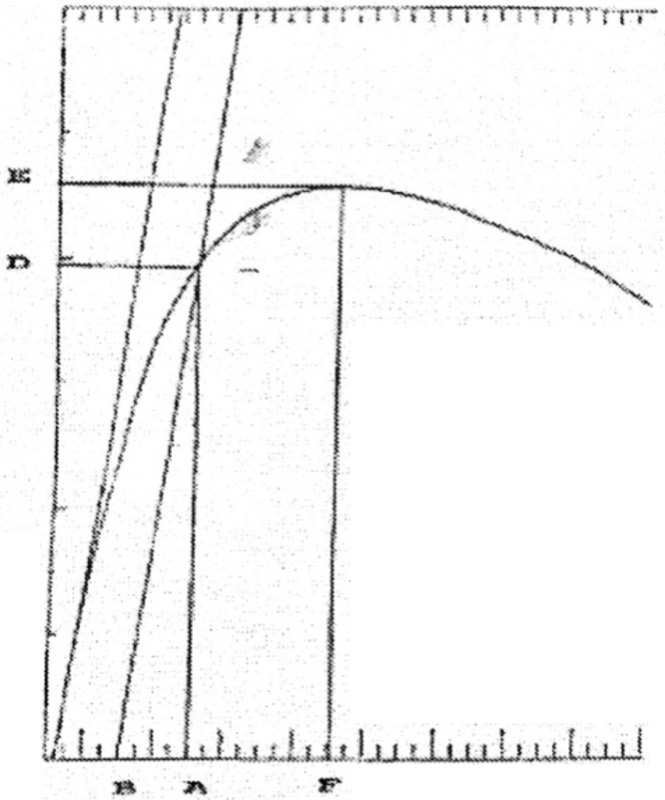
Typical load-displacement curve.
Results
Fig. 3 shows the curve Load versus Displacement obtained for samples 018565- (1–2)
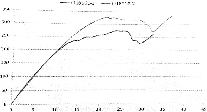
Curve load versus displacement obtained.
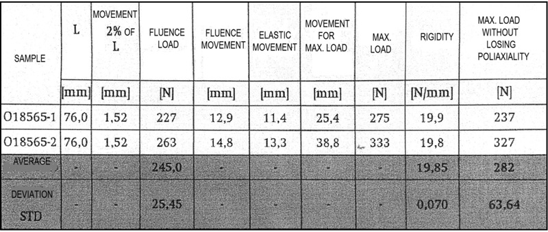
In Table 2 the results are described.
Assay results
Conclusion
Screws and prisoners remained adjusted and there were not apparent permanent deformation in any of the system components. Its cylindrical thread and conical soul provides a high strength profile improving primary fixation and the resistance to the pull out. The major diameter of the soul in the pedicle region increases the bending and the resistance in fixations without arthrodesis preventing the breaking of the screw. All tests were performed within the framework of Management System for Quality Assurance of INTI-Mechanics.