
Abstract
Microinjection is the most flexible transfection method in terms of choice of reagents to inject into cells. But this method lacks the high throughput to compete with less flexible methods like chemical- or viral-based approaches. Various approaches have been pursued to increase the throughput by automating the microinjection process. However, these approaches focused solely on the microinjection itself and disregarded the tasks before and after the injection, which also belong to the critical time path of the whole process, that is, sorting out viable cells from a cell suspension, placing the cell for injection, and collecting the cell after the injection. In the approach with our XenoFactor, we demonstrate a system capable of running the whole process automatically. By optimizing the XenoFactor for Xenopus laevis oocytes, we could demonstrate the successful automated injection. Starting from a suspension with a mixture of defolliculated oocytes at different stages and quality levels, the manual approach requires 1 day in total for the preparation of 400 microinjected oocytes. The XenoFactor takes only 4 h for the same amount and delivers injected oocytes of reproducible quality and without the fatigue symptoms experienced during the manual approach.
Keywords
Introduction
Cell-based assays/models are set to become the preferred choice of screening in drug discovery research, potentially overtaking more traditional approaches that include animal models. 1,2 New target screening often requires the use of cell assays to detect specific cellular pathways of chemical compounds, therapeutic proteins, short interfering RNA (siRNA) agents, and other structures of interest. Insights from these assays could help more efficient discovery of effective drugs, thus saving time and costs as well as the need for future secondary screens.
One of the first steps in cell-based assays is to transfect cells with certain compounds for later testing. The introduction of DNA, siRNA, or other substances into cells is one important micromanipulation technology applied to develop and optimize various cellular systems, which enables cell systems either to more closely approximate in vivo testing or to become more competent or more specific for various in vitro applications. However, industrial customers need a high-throughput, an efficient, and an automated system for direct delivery of substances (including compounds, DNA, siRNA, and monoclonal antibodies [mAbs]) into a large number of cells for HTS use.
The current methods used for either transporting the substances through the cell membrane or inserting DNA, siRNA, mAbs, and other substances into living cells fall naturally into three categories: (1) chemical techniques that rely on carrier molecules; (2) viral vectors used by biologists to deliver genetic material inside a living cell by infection; and (3) physical procedures that introduce material directly into cells. All these three methods have advantages and disadvantages in specific types of application as shown in Table 1.
Summary of current transfection methods based on the publication of Sakai et al. 3
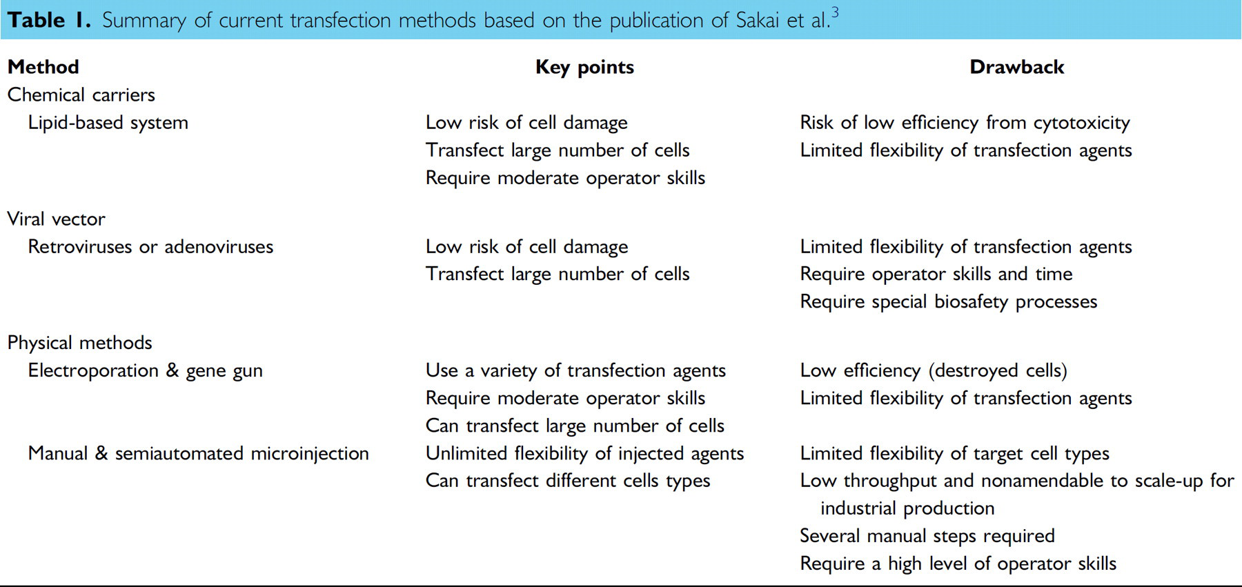
Table 1 shows that although microinjection offers the highest flexibility in the scope of materials to be injected, existing microinjection systems have the following shortcomings: (1) requires a high level of operator skills; (2) low throughput; and (3) several manual steps.
There are, however, very good reasons to use an improved microinjection approach. It allows the introduction of molecules into a defined cell population at a known concentration, and the timing of the experiment can be controlled stringently. Additionally, microinjection offers to introduce several types of reagents into cells simultaneously; for example, DNA constructs coinjected with a fluorescein-labeled dextran to mark the injected cells and a wide variety of reagents, such as antibodies, peptides, siRNAs, dyes, and chemical substances.
Based on the limitations of current delivery methods and on the huge market needs, a new system should have the ability to enable high-throughput direct transfection of a large number of cells with a wide variety of transfection compounds, and therefore to make it an ideal solution to eliminate the difficulty, labor intensiveness, and expensiveness of current cell-based screening techniques.
Several ways of automating the microinjection process were published in the past years. The systems differ if designed for adherent 4,5 or nonadherent cells. Here, we focus onto the nonadherent cells, meaning cells in a suspension. Typically, adherent cells can be brought into suspended form by trypsinization. So far publications for cells in suspension mainly focused solely on the injection process, either by assisting the user for a more successful injection 6 or by fully automating the injection process with a camera/microscope system to localize cells and needles 3,7 or simply a blind injection. 8 Some systems additionally use force sensors 9,10 or impedance sensors 4 to verify the injection or use vibrating piezo elements for a more gentle injection. 6 The impedance sensor can further be used to detect broken needles while running the system. Some teams further investigated the single-cell manipulation by transferring the injected cells into specific wells for subsequent single-cell analysis. 11 But for all the presented systems, a large amount of cells have to be presented either in a petri dish or have to be prepositioned on a special matrix. These systems then have to locate a cell to perform the injection.
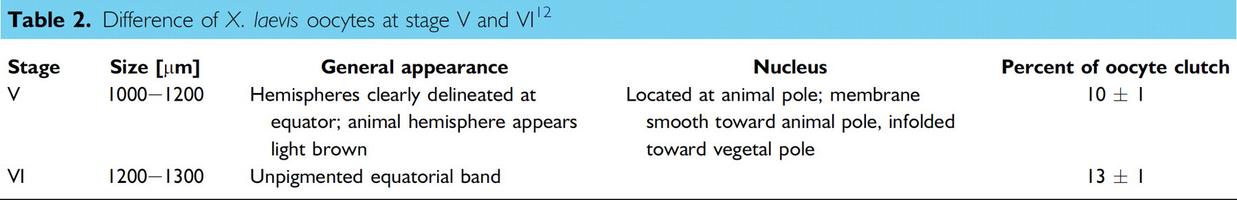
In this publication, we present our XenoFactor, a fully automated microinjection system that sorts viable cells out of a suspension, delivers them to the injection system where the microinjection takes place, and finally collects the cells. Thanks to the modularity of our approach, the cells can even be collected separately for later single-cell analysis. The difference of our system to the above-mentioned systems is that sorting, delivering, and collecting are integrated into one synchronized system. Furthermore, all these tasks can be run in parallel (simultaneously) for individual cells because the system is based on a carousel principle, which results in time saving. The XenoFactor presented here is designed for large cells like Xenopus laevis oocytes but could be easily adapted to other large cells, such as Zebrafish eggs. The concept of the XenoFactor requires minimal amount of manual steps, that is, loading the defolliculated oocytes and adding the pre-filled injection needle. In Table 2, properties of the X. laevis oocytes at stage V and VI are summarized. These oocyte stages have a heavier vegetal pole than animal pole; thus, if the oocyte is put in liquid, the oocyte will automatically start to orient with the animal pole on top.
Difference of X. laevis oocytes at stage V and VI 12
System
Our XenoFactor is designed to sort, dose, immobilize, inject, release, and collect Xenopus oocytes as shown in Figure 1. For these tasks, a CellSorter and Celllnjector system are combined (Fig. 2). In the following sections, the CellSorter and Celllnjector are described in more detail.
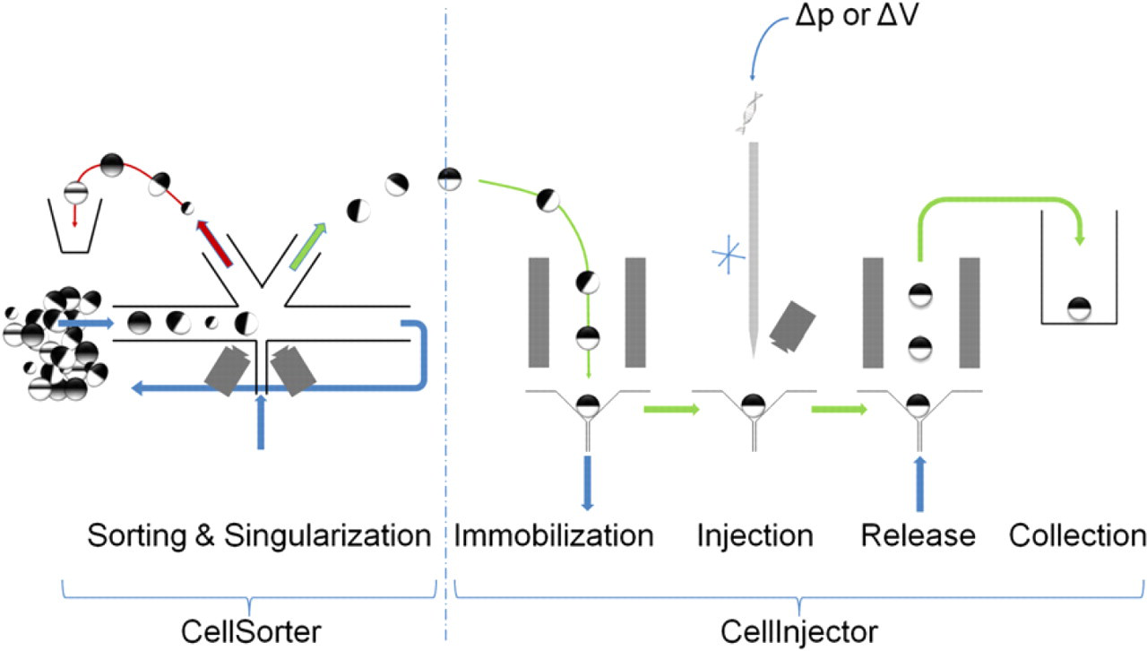
Concept of XenoFactor working with two modules. The CellSorter is loaded with a suspension with a mixed population of different stages of oocytes of varying quality. A chosen class of oocytes of defined stage and quality can be automatically selected and delivered on demand to the Celllnjector. The Celllnjector immobilizes, injects, releases, and collects individual oocytes at respective positions in a carousel. Additionally, stage V and VI oocytes will self-orient at the immobilization site.
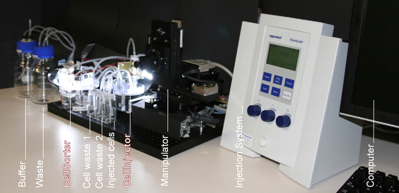
Complete view of the XenoFactor showing the CellSorter and the CellInjector combined with an X-Y-Z-manipulation stage and the Eppendorf FemtoJet injection system. Bottles for fresh buffer supply and waste are also part of the system.
CellSorter
The CellSorter was described in a previous article; 13 therefore, only the basics of this system are discussed here.
The CellSorter is an imaging-based fluidic sorting system. Cells are constantly moved in a closed ring by drag and friction forces. An opening allows the user to continuously add cells while the process is running. Images of the cells are acquired as they pass the imaging system (Fig. 3), and they are analyzed by a dedicated vision algorithm. If a cell is classified as viable (in case of a Xenopus oocyte, the correct size as in Table 2 and the general appearance), it is removed by a gentle liquid stream and transported to the interface, which is described later in more detail.
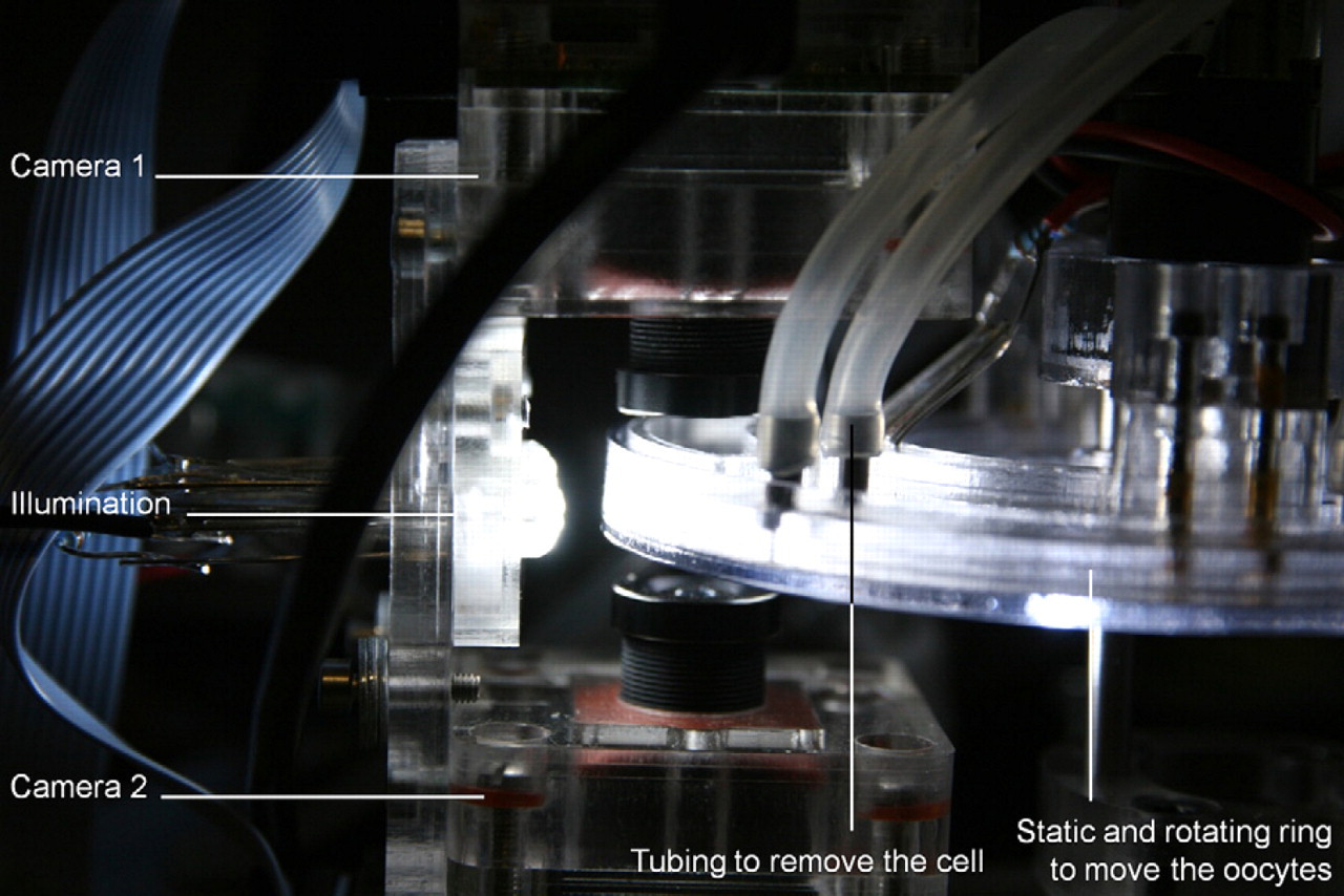
Side view onto the CellSorter showing two cameras, facing each other, with the static and rotating ring in between. Tubing is attached to the static ring such that oocytes can be removed by a gentle liquid stream achieved by redirecting liquid.
The cell classifier can easily be adapted for different kind of cells. The only thing necessary to train the classifier on is a large amount of images of depicting oocytes with the chosen characteristics. Once the classifier has been trained, the time required for the analysis of an individual cell is less than 20 ms, which allows the sorter to characterize cells in real time.
CellInjector
The design of the CellInjector was conceived to accommodate conventional microinjection systems, simply to reach a faster user acceptance and to allow users to upgrade their manual equipment. For example, an x–y–z-needle manipulator (e.g., MP-285; Sutter Instruments, Novato, CA) and injection system (eg., FemtoJet, Eppendorf, Hamburg, Germany) were integrated intoafully automated vision-controlled CellInjector. By small modifications, other injection systems (e.g., NanoJect; Drummond Scientific Co., Broomall, PA) or different automated manipulators (e.g., USAutomation, Laguna Hills, CA) can be combined with our CellInjector.
To increase the throughput of the serial cell injection process, a carousel-based immobilization and transport system was introduced. This allows us to prepare a cell (e.g., orient and immobilize) while another cell is injected and a third is postprocessed (e.g., released and collected). A semidisposable plastic dish with five immobilization sites is placed on top of a rotation table (DT-80, miCos GmbH, Eschbach, Germany) as shown in Figure 4.
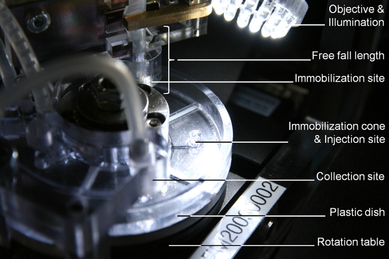
Close-up of the CellInjector showing the immobilization site, injection site, and collection site. The injection needle is not shown for clarity.
The immobilization site design depends on the cell size. For large cells like Xenopus oocytes where gravitation cannot be neglected, a cone-shaped structure is the preferred design as shown in Figure 1. The preferred angle (β) is 90°, which is a trade off between immobilization strength (the smaller the angle, the better the immobilization) and space (the bigger the angle, the smaller is the necessary depth of field and field of view of the camera) as shown in Figure 5. Fluidic connections can be attached at the tip of the cone to apply either positive or negative pressure for immobilization or removal.
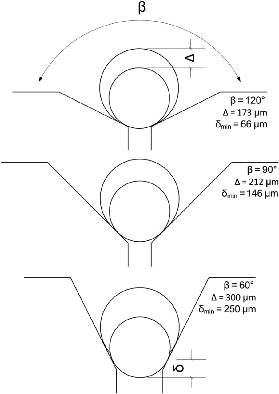
Relation between opening angle β of immobilization cone and critical distance Δ to still have the oocyte in the field of view (as small as possible) and the distance δ to have an as good as possible immobilization of the oocyte (as large as possible). In our current design, we chose β = 90°.
A special design was necessary to connect the immobilization cones on the rotating plastic dish with stationary fluidic connectors (as shown in Fig. 4). A compression seal and additional sealing ring were used to achieve a leak-free sealing between the rotating and stationary parts. The design allows one to apply positive or negative pressure onto the immobilization cones in the appropriate positions.
The connection between the CellSorter and the CellInjector is done by the interface shown in Figure 6. This interface is filled with buffer and acts as a pressure lock by using two custom-made pinch valves and a light barrier to uncouple the two independent liquid systems of the CellSorter and CellInjector. Only one pinch valve may be opened at a time. To guide an oocyte through the interface, pinch valve 1 is initially opened. An arriving oocyte diverges, driven by gravity, in the cell elutriator from the CellSorter liquid system into the liquid system of the interface (see Fig. 6). The oocyte then passes the open pinch valve 1 and finally sets off the light barrier, which triggers the closing of the pinch valve 1 and opening of the pinch valve 2.
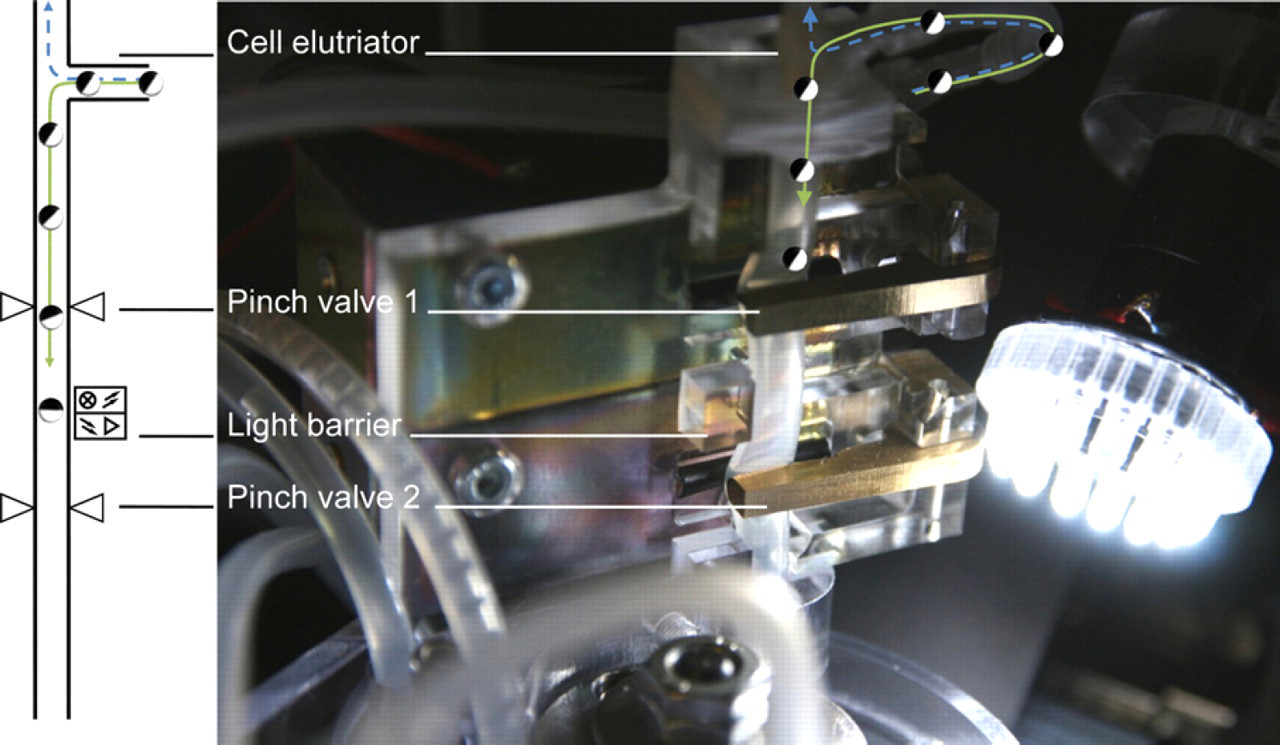
Sketch and close-up of interface connecting CellSorter with CellInjector. The interface consists of a cell elutriator where the oocyte falls down the tubing (green path) driven by gravity, while the buffer is rising up (blue dashed path) drawn by a pump. The oocyte passes then the first pinch valve, which is normally open. On passing the light barrier, the oocyte triggers the closing of pinch valve 1 and the opening of pinch valve 2. The oocyte then orients itself along the free fall length as indicated in Figure 4.
To take advantage of the special property of the stage V and VI Xenopus oocyte, which have a heavier vegetal pole than animal pole, a 30-mm free fall length is introduced between the pinch valve 2 and the immobilization site submerged in buffer. This free fall length allows the stage V or VI oocyte to orient itself such that the animal pole (dark-colored pole) faces upside. Test showed (see Fig. 7) that all stage V oocytes (n = 33) orient themselves within 30 mm. This allows one to inject either into the cytoplasm or the nucleus within an oocyte by controlling the penetration depth of the injection needle.
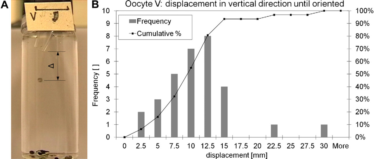
(A) Setup for measuring the free fall length for complete self-orientation of stage V oocytes in water. After 15-mm free fall, more than 90% of the oocytes have the animal pole facing up. The outlet nozzle, where the oocyte starts with the free fall, is specifically bended to force the oocyte to roll slightly for later reorientation. Bar indicates 10 mm. (B) Graph showing experimental results of free fall length for complete orientation determination. Lot size was 33 oocytes.
A CMOS camera (uEye UI-1223LE-M, IDS Imaging Development Systems GmbH, Obersulm, Germany) in combination with a telecentric objective (VS-TC1.5–40, VS Technology Corp., Tokyo, Japan) monitors the injection site and is used for vision control (Fig. 8). This enables to locate the orifice of the injection needle, measure the dispensed volume from the needle, and check the position and orientation of the cell. The whole vision processing is written in C# and uses the Matrox Imaging Library (MIL8.0). The orientation of the oocyte and injection movement of the needle are in the vertical direction, and the camera is placed at an angle (a) of 45° to the injection axis. This setup allows the camera to observe the immobilized cell and the injection needle. The position of the injection needle is determined by an autofocusing algorithm with an accuracy of ±70 μm.
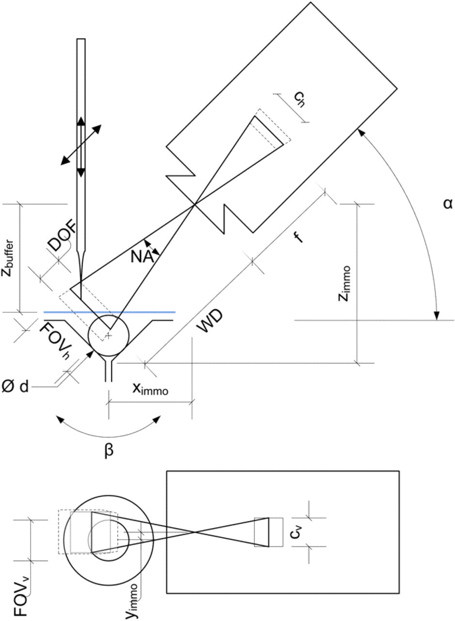
Side and top view of the camera setup for monitoring the injection needle and immobilization site filled with an oocyte. The relative position of the immobilization site (x immo, y immo, z immo) and the buffer height (zbuffer) with respect to the camera have to be set once. The field of view (FOVh × FOVv) and the depth of field (DOF) depend on the working distance (WD), focal length (f), quality of the objective used, and chip size (ch × chv) of the camera. The camera with objective is positioned at an angle a with respect to the horizontal. The immobilization site has an opening angle β, and the oocyte has a diameter d. To track the injection needle, first it is moved in z-direction until detected in the FOV, following a combined movement along the optical axis (x–z-direction) for focusing. Note that only for simplicity of this drawing the distortion of the optical path because of the interaction with the buffer is neglected.
Both the CellSorter and CellInjector are connected to additional pumps, which allow an automated filling within 3 min and emptying within 5 min.
The software of the system assigns a batch number and incremental number to each oocyte to ensure total traceability. For each oocyte, the images from the sorting and injection are taken and the start and end time as well as the quality and all parameters used for this one oocyte are noted.
Graphical User Interface
The graphical user interface (Fig. 9) is kept as simple as possible. The user has to choose the stage of the oocyte, amount of oocytes to inject, place for injection (nucleus or cytoplasm), and volume of matter to inject. To start the system, the Start button can be pressed. In case the system was not changed, it is also possible to load the initial data by pressing the LoadData button; this reduces the time for the initial calibration. Additionally, some buttons for troubleshooting are added; for example, if the flow within the sorter brakes down, the PrimeP3 button can be pressed to remove possible air bubbles within the pump, and so on.
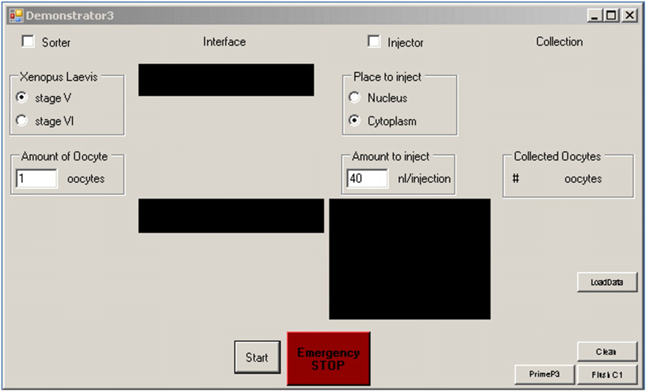
The graphical user interface is designed with a minimal amount of buttons. It is possible to choose the oocyte stage, amount of oocytes to inject, place for injection (cytoplasm or nucleus), and amount to inject. Initially, either the Start button or the LoadData button can be pressed. The system then starts to fill automatically and proceeds with the process. On the lower right are additional three buttons for troubleshooting.
As mentioned before, the data to trace the oocyte sorting and injecting are stored within an XML file, which can be opened separately. Furthermore, a settings file exists, where most parameters can be adjusted; for example, the cell size, parameters for sorting, and others.
Validation
To validate the system, several batches of oocytes were processed with the system. Complementary RNA (cRNA) was injected into the cytoplasm and used to confirm the successful injection by observing the expression of channel proteins after an incubation time of 36–48 h.
Method
X. laevis larvae were raised at the Center de Ressources Biologiques “Xenope” at the University of Rennes 1.
Oocytes were surgically removed from narcotized X. laevis, washed in modified oocyte ringer 2 (OR-2) buffer (NaCl 82.5 mM, KCl 2.5 mM, CaCl2 1 mM, MgCl2 1 mM, N-(2-hydroxyethyl)piperazine-N'-ethanesulfonic acid 5 mM), defolliculated by collagenase treatment with calcium-free OR-2, and finally washed again in OR-2. 14
Materials used for the process were glass petri dishes and glass transfer pipettes for oocyte handling, and Eppendorf Microloader (5242 956.003, Microloader, Eppendorf, Hamburg, Germany) to load the Eppendorf CustomTips (5175 110.005, unsterile, borosilicate glass, A 10 um, D 0°, Custom-Tips, Eppendorf, Hamburg, Germany) for microinjection. The oocytes were kept in modified OR-2 buffer during incubation.
The oocytes were kept in an incubator at 16 °C before and after the injection process. During the process, the oocytes were exposed to a room temperature of 17 °C.
To check the survival rate of the oocytes in the CellSorter, about 40 oocytes from stage V and VI were introduced and stored for 2 h in the CellSorter. Images were taken before and after the storing procedure. A control group was used as a comparison.
To test successful microinjection, human organic anion transport protein (OATP2) cRNA 15 was transcribed in vitro from a plasmid containing the human OATP2 cDNA (provided by Professor D. Keppler, DFKZ, Heidelberg, Germany) and injected into the cytoplasm of the oocytes by using the NanoJect II. The injection volume was 50 nL, which corresponds to 10 ng/oocyte. After the injection, the oocytes were incubated between 36 h and 48 h at 16 °C to allow the protein expression. The oocytes were then transferred in a multiwell plate, washed twice with OR-2 buffer, and incubated for 1 h with various concentrations of radiolabeled substrate (estrone-3-sulfate). The uptake was stopped by the addition of ice-cold OR-2 buffer. The oocytes were then washed four times with ice-cold OR-2 buffer, transferred in liquid scintillation counting vial, lysed with 10% sodium dodecyl sulfate, and the associated radioactivity was measured. In the uptake study with different concentrations, batches (two or three oocytes) were lysed together for analysis. In the uptake study for repeatability, single oocytes were lysed and analyzed. The control of un-injected oocytes was left at 16 °C, and later treated in the same way as the injected oocytes for radioactivity measurement.
Manual injection was done similar to the uptake study for repeatability described above but with a different batch of oocytes at a later date.
For a time comparison between the automated injection (XenoFactor) and the manual injection, the times required for the different steps were measured and reported.
Results
Oocytes (stage V or VI) placed for 2 h in the CellSorter running at normal speed were compared with a control group stored in an incubator. Viability was checked visually 24 and 48 h after the manipulation in the CellSorter by looking at the oocytes' roundness and coloring. Oocytes with perfectly spherical shape and a clear contrast between the darker animal and lighter vegetal pole, without contrast patchiness, were considered viable. No significant difference was found between the two batches of oocytes (Fig. 10). After 48 h, 97% of the control oocytes were viable versus 97% or 94% for stage V and stage VI oocytes placed in the CellSorter, respectively.
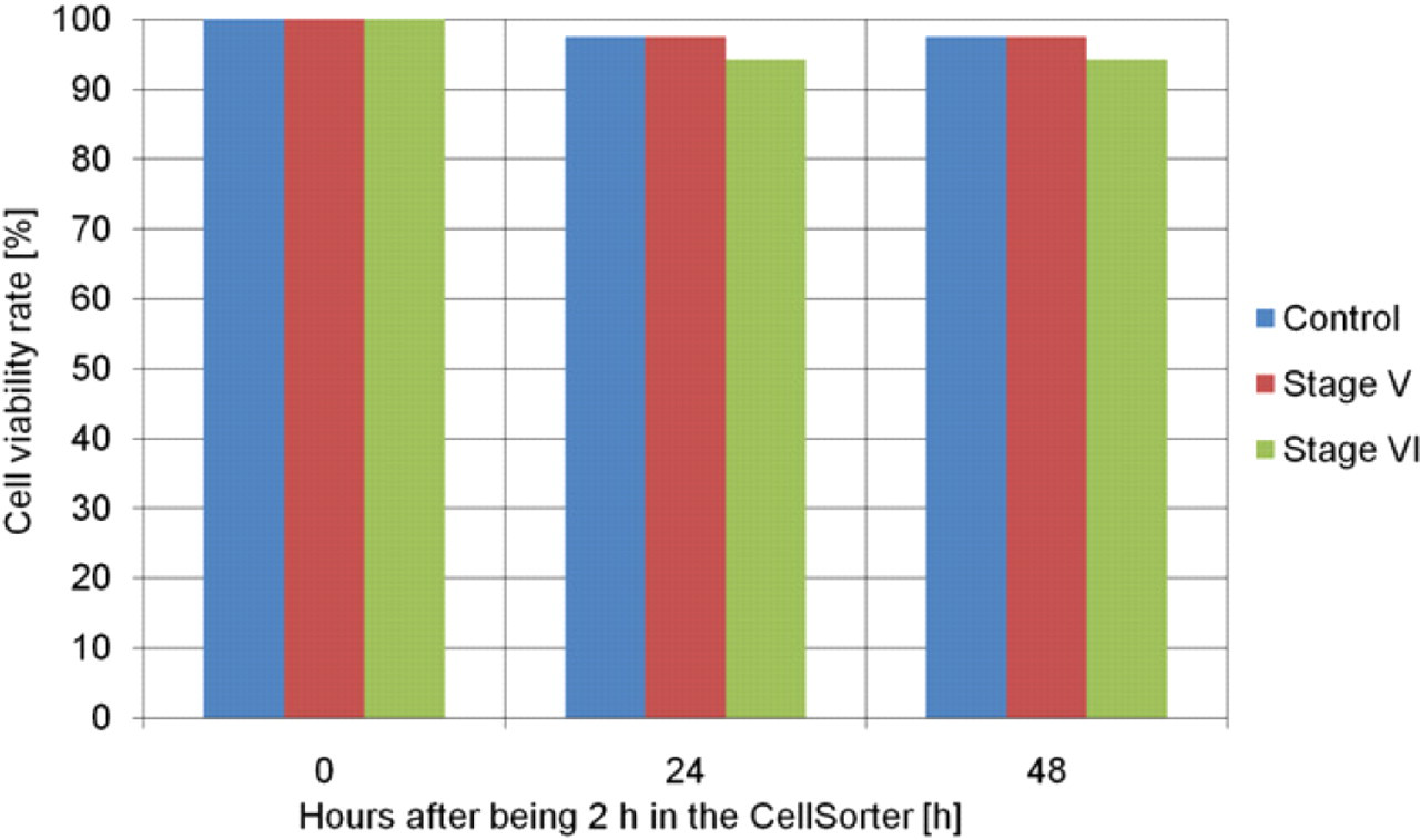
Cell viability study of oocytes being manipulated for 2 h within the CellSorter (control: 40 oocytes [mix of stage V and VI], stage V: 40 oocytes, stage VI: 35 oocytes).
For the verification of the whole XenoFactor system, 350 stage VI oocytes were injected with OATP2 cRNA, whereas another 100 stage VI oocytes were kept as a control. The injection took place 24 h after the oocytes preparation. The oocytes were then incubated for 36–48 h to allow protein expression and finally tested in an uptake study. Figure 11 shows the result of this study at different substrate concentrations, whereas Figure 12 presents the repeatability of the uptake study. Additionally, Figure 12 shows normalized concentration values of automated and manual injection to compare expression repeatability of oocytes.
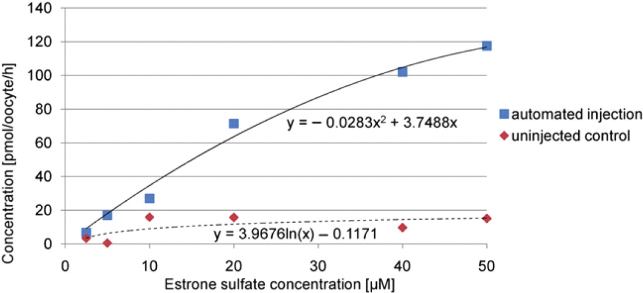
Uptake study of oocyte batches at different estrone sulfate concentration for 1 h. Fitting curves show the trend of the individual measurements.
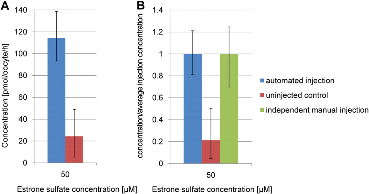
(A) Repeatability study with single oocytes (six injected controls and four uninjected controls) exposed to a 50-μM estrone sulfate concentration for 1 h. (B) Repeatability study normalized to compare with independent manual injection. Error bars indicate minimum and maximum values of the measurements.
The average cycle time of an oocyte was within 35 s, whereas sorting and singularizing took 5 s, delivery took 10 s, injection took 10 s, and the release took another 10 s. Because of current software limitations, multithreading was not possible, meaning the different manipulations could not be performed simultaneously; the hardware, however, is already prepared for multithreading.
Discussion and Conclusion
Cell transfection is a daily business in drug discovery, toxicity screening, and so on. Among the various transfection methods, microinjection remains one of the most effective transfection methods. However, it lacks in efficiency and repeatability because the process is still done manually. Moreover, the semiautomated microinjection systems available nowadays only focus onto the microinjection itself. The analysis of the manual microinjection process shows that additionally to the microinjection also surgical removal, defolliculation, sorting, and singularization are bottle necks, which should be improved. The XenoFactor, the fully automated microinjection system presented here, includes sorting and singularization of viable cells, their transfer between modules, injection, and finally the collection of them. The XenoFactor was optimized for X. laevis oocytes but can easily be adapted to other biological samples of similar size like Zebrafish larvae or others. The system consists of the CellSorter and CellInjector but can also be coupled with the WellPlateFeeder or any other subsequent system to add additional functionality.
We verified experimentally the effectiveness of the Xeno-Factor as a fully automated microinjection system. Results showed that oocytes manipulated for 2 h within the Cell-Sorter (sorting device of the XenoFactor) aged similar to a control. To verify the CellInjector, OATP2 cRNA was injected and after a 36–48-h incubation time, the expected expressed human organic anion transport proteins were tested by an uptake study, which proved that the expression and so the automated injection were performed successfully with similar expression variability compared with manual injection.
So far at the University of Rennes 1 the manual injection of 400 oocytes took two working days. The first day was used to surgically collect the oocytes, decollagenase them, and finally sort them. Because of fatigue reasons of the technician, the oocytes were then incubated until the second day. The second day was used to sort out dead oocytes and inject the viable oocytes. Finally, the injected oocytes were collected and ready for the 48-h incubation. In Figure 13, the average time for a single oocyte is listed next to the individual steps of the microinjection process calculated from the above-mentioned time steps. In summary, by using the XenoFactor, we were able to reduce the microinjection of a batch of 400 oocytes from previously 2 days (manually by one technician) to less than 1 day (automated by the XenoFactor).
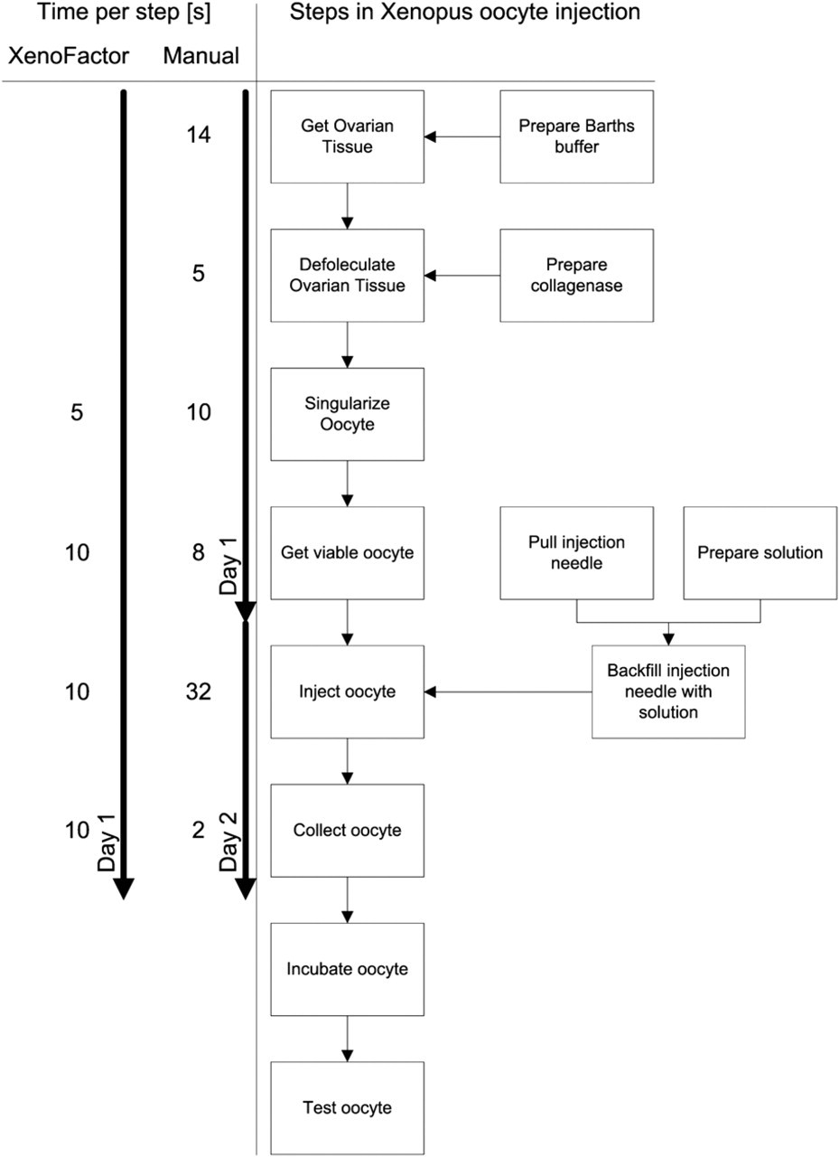
For each step in the microinjection process, the average time for one oocyte is listed. Where applicable, the average time for the XenoFactor is also shown. The average time for the manual injection process is calculated from the preparation of a batch with 400 oocytes.
Furthermore, technicians are less exhausted and can perform other work at the same time.
The current cycle time in the XenoFactor for a single oocyte is 35 s. In a future step, the software will be adapted to perform the sorting, singularization, injection, and collection of four oocytes simultaneously, which will lead to a cycle time of less than 10 s per oocyte.
Acknowledgments
Special thanks to the team of Francois Verrey from the University of Zurich, especially to Ian Forster and Eva Hänsenberger for the supply with fresh oocytes and buffer as well as the good discussions. We also thank the European Commission for supporting this project within the integrated project Hydromel NMP2-CT-2006–026622.
Competing Interests Statement: The authors certify that they have no relevant financial interests in this manuscript and that all financial and material support for this research and work are clearly identified in the manuscript.