
Abstract
Manipulation of biological cells becomes increasingly important in biomedical engineering to address challenge issues in cell—cell interaction, drug discovery, and tissue engineering. Significant demand for both accuracy and productivity in cell manipulation highlights the need for automated cell transportation with integrated robotics and micro/nano manipulation technologies. Optical tweezers, which use highly focused low-power laser beams to trap and manipulate particles at micro/nanoscale, have emerged as an essential tool for manipulating single cells. In this article, we propose to use a robot-tweezer manipulation system to solve the problem of automatic transportation of biological cells, where optical tweezers function as special robot end effectors. Dynamics equation of the cell in optical tweezers is analyzed. A closed-loop controller is designed for transporting and positioning cells. Experiments are performed on live cells to demonstrate the effectiveness of the proposed approach in effective cell positioning.
Introduction
Most of the existing cellular researches focus on studies with large cell populations, which unfortunately lose information about dynamic behavior of individual cells and heterogeneity within the populations in the process of averaging cellular responses. 1 A study at single cell level not only provides complementary information but also reveals the actual functional interaction of biomolecules on the cellular and tissue structural basis.2–7 In the study, reproducibly transporting and positioning biological cells at micro/nano precision level for further analysis is the first critical step.8–10 Many techniques have been developed for manipulation of single cells, such as micropipette aspiration, atomic force microscope (AFM), electrokinetics (electrophoresis, dielectrophoresis), magnetic tweezers, 11 hydrodynamic flows, and optical tweezers, 12 to name a few. Although micropipette aspiration has been widely used in applications, 4 it may damage the cell membrane or cytoskeleton easily. 13 Using an AFM probe, a variety of tasks such as pushing, pulling, cutting, and indenting can be realized. But for more complex manipulation tasks such as rapid pick and placement, more complex configurations with real-time monitoring system and chemically activated and controlled probes are needed. Electroki-netic forces have been used for single cell positioning, but they are difficult to be used in high ionic strength cell-culture medium. Other tools such as magnetic tweezers and hydrodynamic flows have exhibited advantages of high throughput for manipulation of cells, but lacked flexibility or spatial resolution necessary for controlling individual cells. 14
Using the forces exerted by a strongly focused beam of light, optical tweezers can function as special robot end effectors to trap and move objects ranging from tens of nanometers to tens of micrometers. Optical tweezers have been gaining increasing attentions for their advantages of precise, flexible, and noninvasive manipulation of objects in liquid-medium environments, which is very important to biological samples. Despite the problem of photodamage, optical tweezers have been widely used in biomedical fields, such as micromanipulation of somatic cells and gametes, investigation of vesicle motility, and the developmental studies on ciliated cells.15,16
Currently most of the optical tweezer systems use a mouse or a stand joystick to control the optical traps. While possessing advantage of robustness, manual manipulation cannot be efficiently used for applications that require precise manipulations of large numbers of cells repetitively. 17 A few works have been done toward automatic manipulation of optical trapping,18–21 in which, however, the open-loop control strategies were adopted to move cells, along with predesigned collision-free paths. To the best of our knowledge, little work on the closed-loop control demonstration of optical tweezers has been reported in the literature. Closed-loop control is important to improve precision, throughput, and robust-ness,22,23 which is a key to many biological manipulation processes such as cell fusion, cell microsurgery, and assembly of biological sensors. In addition, automatic computer control allows us to manipulate multiple traps simultaneously, which will significantly improve the throughput.
In this article, we propose a new approach to incorporating robotics technologies, such as machine vision and closed-loop control algorithms, into optical tweezers for automated transportation of biological cells. This study has many bio-medical relevances. One application example is cell sorting, which has significant potentials in drug discovery, tissue engineering, and fundamental cell biology. Another example is cell microsurgery, where the cells need to be precisely positioned at the defined locations, and the laser microbeam is used to ablate unicellular organisms, cells, and subcellular structures (mitochondria, nucleolus, chloroplast, and so on) such that their corresponding functions can be investigated. 24 Additionally, rapid and precise transportation of cells can benefit the fabrication of pharmacophore-erythrocyte complexes, 20 cell-cell interactions, cell fusion, and so on.
The remainder of this article is organized as follows. In the next section, the robot-tweezer manipulation system is introduced, which is followed by dynamics analysis of the cell in the optical trap. In the fourth section, a closed-loop controller is designed for automatic transportation of single cells. Experimental studies are reported in the fifth section. Finally, conclusions of the work are given in the last section.
Robot-Tweezer System
To achieve automatic manipulation of biological cells, we establish a robot-tweezer manipulation system in laboratory, as shown in Figure 1. The system contains three subsystems for execution, sensing, and control. The executive subsystem consists of an X-Y-Z motorized stage (ProScan; Prior Scientific, Rockland, MA) and a holographic optical trapping (HOT) device (BioRyx 200; Arryx, Chicago, IL). The stage is used to carry and displace the tissue-culture dish, which can be controlled either manually using a joystick or automatically through a serial port. In the HOT device, a liquid crystal spatial light modulator (SLM) is used as the actuator, which imprints computer-generated holograms onto laser's wavefronts. Then, the phase-modified laser beam is transferred by relay optics to the input pupil of an inverted objective (Plan Apo 60 ×/1.20; Nikon, Tokyo, Japan) and focused into holographic optical tweezers.
25
The optical tweezers function as robot end effectors to manipulate cells. The sensory subsystem consists of a microscope and an IEEE 1394 digital camera (FO124SC; FOculus, Finning, Germany). A dichroic mirror reflects the laser light into the objective while allowing images of the trapped cells to pass to the camera. Positions of biological objects can be obtained through image processing. The control subsystem receives the visual feedback from the charge-coupled device (CCD) camera and generates outputs. All of the mechanical components are supported on an antivibration table in a clean room.
Robot manipulation system with optical tweezers. (A) Schematic illustration. (B) Experiment setup.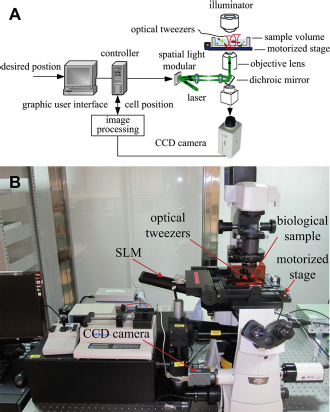
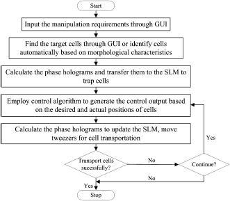
Control software is developed in Visual C++ 6.0 to enable dexterous manipulation of biological cells. The graphical user interface (GUI) is shown in Figure 2. A modular architecture is used, which consists of a GUI module, a laser control module, a SLM control module, a motorized stage control module, a camera control module, and a main controller module. The cell manipulation procedures are described in Figure 3.
GUI of the control software. Cell transportation procedures with the robot-tweezer system.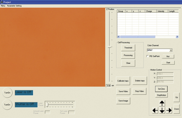
Dynamics Analysis
Optical Trap
The robot-tweezer system uses a SLM to split a single colli-mated laser beam into several separate beams, and each single laser beam can be placed anywhere within the focal volume of the objective lens. The actual position of the trap is assumed to coincide with the required position perfectly after calibration.
There are mainly five forces exerted to an optically trapped cell: optical force, gravitational force, buoyant force, viscous drag force, and Langevein force. For convenience, we divide the optical force into two parts, force along the Z-axis (optical force in Z-axis direction) and force in the X-Y plane (optical trapping force). The forces in Z-axis, including optical force in Z-axis direction, buoyant force, and gravitational force, can get balance for a stable optical tweezer system. While discussing the motion of the trapped cell in the X-Y plane, the forces in Z-axis have no direct contribution to the lateral motion, and thus can be ignored.
26
In the transportation process, Brownian motion caused by the Langevein force is relatively small, and hence the Langevein force can also be neglected. Therefore, the forces that govern the motion of the trapped cell mainly consist of the trapping force from optical trap and the viscous drag force from liquid, as shown in Figure 4.
Schematic diagram of a cell in an optical trap.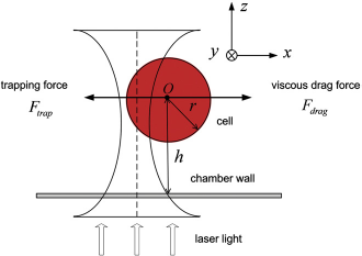
The equation of the motion of the cell in the lateral plane is:

where m is the cell's mass,
As is known, the effect of the inertia force
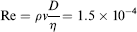
where ρ is the density of the suspending medium, and η is the viscosity of the medium. Because Re < <1 in the study, the inertia force can be neglected.
27
As a result, Eq. (1) is simplified as:

Trapping Force
The trapping force applied by a laser beam to the cell is customarily defined as follows
16
:

where Q is a dimensionless efficiency factor, which depends on the numerical aperture of the objective, laser wavelength, light polarization state, laser mode structure, relative index of refraction, and geometry of the particle, 16 nm is the index of refraction of the suspending medium, P is the incident laser power, and c is the speed of light.
Because diameters of cells are usually quite larger than the wavelength of the trapping laser (1064 nm), for example, the diameters of yeast cells used in this study are about 5—6 μm, the ray-optics model can be used to calculate the trapping force. According to the method and the intensity profile of the laser beam as reported in,
28
we can obtain numerical solution of the force, which is a function of the offset between the trap center and the cell center. Taking the radius of the yeast cells for an example (radius is 3 μm), we obtain the trapping force as shown in Figure 5, where r0is the critical deviation or offset when the trapping force begins to decrease as the deviation increases. The parameters in the calculation are as follows:
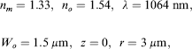
where no is the refractive index of the cell, λ is the wavelength of the laser beam, Wo is the radius of the beam waist, r is the radius of the cell, and z is the distance from the cell to the minimum beam waist.
28
It is seen from Figure 5 that the trapping force is zero when the cell is perfectly centered on the trap because all force components are in balance. The trapping force increases as the offset between the cell center and the trap center increases, in an approximately linear relationship, until the offset is larger than r0. When the offset exceeds r0, the trapping force decreases as the offset increases, and becomes zero when the cell is completely outside the optical trap. Therefore, it is ideal to confine the cell displacement within the range r0in the manipulation.
Example of yeast cell: lateral trapping force vs lateral offset.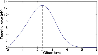
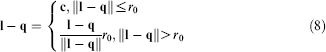
The trapping force can be described as:

where k is the stiffness of the optical trap,
Drag Force
The drag force applied to the cell moving in liquid can be calculated by Stokes’ Law as follows
16
:

where
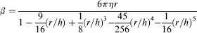
is the drag coefficient, η is the solution viscosity, and h is the distance from the bottom surface of the chamber to the cell center.
Dynamics Equation of the Trapped Cell
Substituting Eqs. (4) and (5) into Eq. (2) yields the dynamics equation of the motion of the cell in optical trap, expressed as:

Eq. (6) can be rewritten as:

It is seen from Eq. (7) that the dynamics of the trapped cell is a first-order system subject to the constraint of ||
Closed-Loop Control
On the basis of the dynamics Eq. (7), we can design a controller for single-cell positioning as follows:
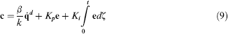

Substituting Eqs. (8) and (9) into Eq. (7), we obtain the following closed-loop dynamics when ||
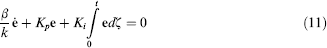
Eq. (11) implies that
Using the controller Eq. (8) — Eq. (9), the cell can move along with the desired trajectory as long as the condition ||
However, being subject to the constraint of ||
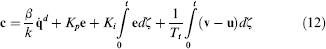
where Tt is the tracking time constant,
Experiments
Experiments are performed to demonstrate the effectiveness of the proposed approach to transporting biological cells. Considering the fact that few calculations or measurements of the full stiffness matrix of nonspherical objects trapped in optical tweezers have been reported in the literature, 30 we mainly considered the transportation of approximately spherical cells here. Yeast cells whose diameters were about 6 μm were used in this study. All the experiments were performed at 37 °C in 5% CO2for cell viability.
Calibration of Parameters
To verify the validity of the dynamics Eq. (7) and choose appropriate parameters for the controller, β and k should be identified first.
It is seen from Eq. (7) that the value of Deviations of the cell from the trap center at various cell velocities.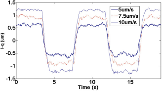
Value of β/k of yeast cell
It is worth noting that to precisely move the cell along the desired trajectory under the constraint ||
Tests
Control of the relative positions of cells has led to new advances in cell—cell interactions and tissue engineering.
32
For example, two species of yeast cells, Hanseniaspora uvarum and Saccharomyces cerevisiae, have been patterned to study the cell growth regulation in microbial ecosystem.
33
Patterning CD4 + T cells and Jurkat T cells has also been used to study the cell—cell interactions between them.
34
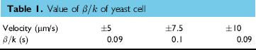
In this article, we applied the robot-tweezer system to create a pattern of yeast cells to test the set-point position control. Figure 7A shows two images recorded with the CCD camera showing the automated assembly process of five yeast cells with prespecified pattern similar to that described in ref. 34. In the experiment, five optical tweezers were created to hold five yeast cells at the initial positions, and then four cells were transported simultaneously toward predetermined positions to form a desired cell pattern as shown in Figure 7A. The arrows in the figure represent the moving directions of the cells. Figure 7B shows the position errors of the four moving cells. The control parameters were Kp= diag{0.4,0.4}, Ki= diag{0.2,0.2}, and Tt= 1, which were chosen by the trial-and-error method.
Automated cell pattern generation using set-point position control. (A) Five yeast cells in pattern. (B) Cell position errors.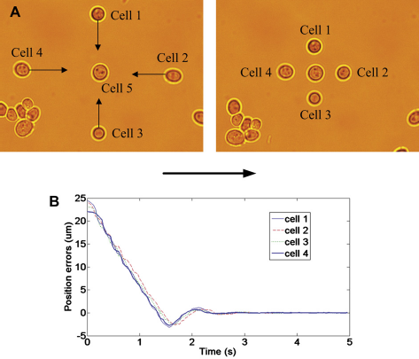
In many biomedical applications, it is necessary to isolate specific target cells that exhibit interesting phenotypes or morphological properties, and then transport them to regions of interest for further analysis,
32
for example, in a lab on a chip. This creates a need for separating cells from their surrounding backing populations. To achieve this, a variety of path planning algorithms, such as A-star algorithm, potential field approach, and a stochastic dynamic programming-based motion planning framework can be used for automatically transporting cells while avoiding collisions with obstacles. Because this article focuses on control design only, we do not discuss path planning and only use a predesigned path in the experiment. As shown in Figure 8A, a target cell was sorted from its surrounding environment along a designed a trajectory 
where Automated cell transportation using trajectory tracking control. (A) The cells in the experiment. (B) Position errors of the cells.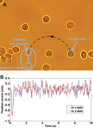
Conclusions
There is a great demand for designing an approach to manipulating single cells precisely and effectively by a robotic manipulation system. In this article, robotics technology is incorporated into optical tweezer manipulation system to transport and position biological cells automatically. Hardware components and control software of the robot-tweezer system are presented. Dynamics of the cell in optical trap is analyzed, which is followed by a closed-loop controller design for precisely transporting cells. Experiments performed on live cells demonstrate the effectiveness of the proposed approach in effective cell positioning. Future work includes extension of cell manipulation from 2D to 3D.
Footnotes
Competing Interests Statement: The authors certify that they have no relevant financial interests in this article and that any /all financial and material support for this research and work are clearly identified in the article.
Acknowledgments
This work was supported in part by a GRF grant from Research Grants Council of the Hong Kong Special Administrative Region, China under grant CityU 120310, and UGC Special Equipment Grant (SEG_CityU 01).