
Abstract
Microarraying technologies have emerged as key tools for determining genomic expression. The quality of gene arrays is reliant on spotting pins for production of uniform spots, which are consistent in volume, shape, size and alignment.
Point Technologies, Inc., has developed an advanced spotting technology. Emphasis has been placed on producing the “perfect spots” customized to each microarraying application. Uniform surface texturing such as highly polished or matte finishes, and hydrophilic/hydrophobic zonal coating is produced using Point Technologies' proprietary micro-machining technology. Micro-fabrication also permits the production of advanced pin designs, and high density, high throughput print-head assemblies of 1536 pins and greater. Point Technologies specializes in the micro-electrochemical machining of spotting pins in any size, shape and configuration.
Presented data will demonstrate spotting pin design solutions, such as: variety of tip dimensions, surface finishes, specialized coatings, and material options instrumental in producing the ideal spot size, shape and spot density during extended usage.
Overview
The recent advances in microarraying instrumentation have enabled researchers to create customized arrays to meet their application needs. The tools are constantly evolving to increase array density, manufacturing speed, throughput, automation, and reproducibility. Microarray technology has empowered researchers to approach gene expression analysis on a genomic and proteomic scale. 8 The fields of functional genomics and proteomics are developing at an accelerated pace and placing new demands on microarray technology. 1 Microarraying robotics, printing substrates, and array scanning technology have kept pace with the demand for new discovery, however, spotting pin technology has lagged further and further behind. The need for microarrayer instruments that maximize flexibility and precision without compromising speed and cost has become critical. 1
Introduction
Contact Printing
Contact printing involves direct contact between the printing mechanism and the solid surface. Contact printing devices include solid pins, capillary tubes, split-pins and micro-spotting pins or “ink stamps”, all of which deliver sample spots onto the solid surface. 9 Current contact printing tends to produce somewhat irregular spots, and there is a practical limit to spot size that can be obtained. 1 Any change in the distance between the printing pins and the print surface will also cause slide-to-slide variations. Spot-to-spot reproducibility is essential for quantitative comparison of genes on an array. 5 The preferred method for deposition onto the slide of the very small (1–100 nanoliter) quantities of liquid involved is to use stainless steel, tungsten, or titanium spotting pins. 9 These may be solid pins, which dispense just once per sample collection action, or split-pins, which pick up a greater amount of fluid at a time and are capable of a multidispensing mode of operation. In either case, the sample is transferred passively by surface tension as the tip touches the slide surface. Contact pin printing is performed by using solid pins and split pins for transferring samples from the microtitre plate onto a flat substrate.
Types of Spotting Pins
Solid pins are typically dipped into a resource well plate, where they pick up a minute amount of a sample by direct surface tension and transfer this sample onto the microarray surface by direct contact. One sample loading makes one spot, sometimes limiting the printing speed. Solid pins are typically easier to manufacture, making them less expensive. They are durable and have a decreased sample carryover. The tips of solid pins are generally flat and the diameter of the pins determines the volume of fluid that is transferred to the substrate. Modification of the tip configuration allows for a customized array of spot sizes to be printed with improved uniformity. 1,2
Split or quill pins use capillary action to wick solution from the resource well plate into a slit cut into the printing pin. Capillary action depends on the forces created by surface tension and by the wetting of the sides of the slit of a spotting pin. Slit or quill pins are able to print multiple spots without going back to the resource plate, which gives them greater throughput when using matching densities of slit and solid pins. Slit pins are more difficult to manufacture than most solid pins due to the 24.5μm — 98μm slit cut into the tip of the pin. They have an increased tendency to clog with sample fluid, which increases the chance of carryover. Split pins are increasingly undesirable with higher viscosity solutions. In addition, split pins are not as durable as solid pins due to deformation of the pin tip with increased touchdowns on the spotting substrate. Pin tips are typically larger due to the split tip and capillary channel. 1
Spot Size
Spot size is a function of the dimensions of the pins, surface tension and viscosity of the spotting solution. 2 Touching the pins onto the slide surface leaves a spot, the diameter of which is determined by the surface energies of the pin, fluid, and slide. Spotting pins produce spot sizes proportional to sample/pin tip surface area. The typical spot size ranges from 100μm to 600μm in diameter. With many solutions, a 100μm tip produces a 180μm spot under ideal conditions (10 nanoliter volume = 300 micron spot size). 9 The size of the spot deposited on the slide determines the number of spots that can be printed on a slide. Spot size is related to the volume of sample deposited on the surface. 2 Spotting pins must possess the proper surface energy/surface tension, contact angle and substrate wettability in order to create suitable adhesion to the printing substrate. 3
Spot Reproducibility
Spot reproducibility is a measure of spot variation during the printing process. Spot variations can be due to mechanical differences between pins, slight variations in the slide surface properties, and changes in the pin during the printing process (clogging or deformation of pin tip). The reproducibility of cDNA arrays depends upon several factors, such as the quality of the printing pins, sample preparation, quality of spotting substrate, the precision of the robotics, contact force, and environmental control. 1
Factors that Effect Spot Reproducibility
Pin Technology
The surface area of the tips that contact the printing surface should be identical. Different tips can produce different sized spots. Hydrophilic / hydrophobic coatings and texturing can also determine the amount of fluid deposited onto the slide. Controlled contact force and pin material properties play a vital part in the reproducibility of the spot.
Sample Preparation
Samples must be homogenous and free of contamination. Particulate contaminants cause poor reproducibility and poor attachment to the array surface. Proteomic spotting solutions tend to have a high viscosity and are virtually impossible to spot using split pins. Solid pins continue to be the “gold standard” for high viscosity solutions due to clogging of split pins.
Spotting Substrate
If the substrate is not homogenous, then different amounts of DNA will attach to the surface. 9 A consistently flat printing surface also ensures consistent sample delivery. The printing substrate's surface wettability plays a large part in determining spotting morphology, uniformity, and reproducibility. 8 Acceptable bonding adhesion is achieved when the surface energy of a substrate (measured in dynes/cm) is approximately 10 dynes/cm greater than the surface tension of the liquid. When the drop formed by the surface tension touches the printing substrate, an angle of contact is formed. This angle represents the surface energy, or wettability of the substrate. Surfaces have energy associated with them because molecular work is needed to form the surface. The larger the surface area, the greater the surface energy. 10 The higher the surface energy of the solid substrate relative to the surface tension of a liquid, the better its “wettability”, and the smaller the contact angle. 10 To minimize energy, most fluids assume the shape of the smallest surface area. 4 In essence, the surface energy is determined by the spotting substrate, pin surface, and the spotting sample's viscosity. Planarity of the printing substrate effects consistency of pin touchdowns and the amount of sample deposited.
Motion Control System
The motion control system requires precise repeatability of at least 5μm in all three directions. The accuracy of the X, Y and Z slides will determine the array uniformity, reduce spot merging and pin vibration. The Z-force must be controlled due to potential damage to pins, especially split pins. 1
If a pin surface contact area is chosen as a means of calibration, the speed at which the pin strikes the surface can affect the spot size if excessive speeds are used. If the pin taps the surface at high velocity, >20 mm/sec, fluidic inertia may force a large volume of the sample out of the pin, resulting in a large spot. Tapping the pins may lead to plastic deformation of the pin tips. Solid pins have better wear performance when using increased contact pressure and Z-speeds. As with most microarray instrumentation, there are tradeoffs between reproducibility and speed. Producing consistent microarrays takes tighter motion and environmental controls.
Spot Morphology
Spot morphology variation affects scanning results. A droplet that spreads more than its otherwise identical neighbor will have a lower area of concentration of dye, and will produce a scan signal that is inversely proportional to the spot area.
Surface Tension
Surface tension is the force at the surface of a liquid due to adhesive forces of the liquid molecules to the tip of the spotting pin and the attractive forces of the molecules of liquid to each other. 4 This force tends to minimize the area of the surface, thus a drop is formed. When the adhesive forces of the molecules to the spotting pin are greater than the attractive forces between liquid molecules, the surface of the liquid will be transferred to the pin, then the surface of the spotting pin is considered wetted, or hydrophilic, and surface molecules tend to cling to it. 3
Environment
The most important factors — humidity, temperature, and dust-must be controlled to obtain the highest quality microarrays. Changes in humidity and temperature can have drastic effects on spot size and quality. Humidity must be controlled to avoid excessive loss of the sample fluids and to prevent concentration of the sample fluids. Humidity also causes corrosion of some metal parts such as stainless steel spotting pins and heads.
Viscosity of the spotting solution is dependent on temperature. At higher temperatures, the viscosity decreases, as the molecules take on more kinetic energy allowing them to move past each other faster. Viscosity produces a resistive force. This resistance force is frictional force acting between parts of the fluid that are traveling at different speeds. Viscosity must be controlled in order to dispense the proper amount of spotting solution. 6

The smaller the biological assay, the cleaner the environment must be. A spec of dust can ruin a microarray experiment. Contaminants on the surface of the spotting pin reduce the net inward force and decrease the surface energy. Dust and airborne contaminates can clog split pins. Environmental control will decrease pin contamination, increase corrosion resistance, ensure proper spotting viscosities and provide a control factor for arraying.
Residue Buildup
Dipping the pins in distilled water and then removing the wash water from the pins with a vacuum cleanses the pins with minimal carryover. Due to the high salt concentrations in samples, residue commonly forms on split pins and mechanically ground pins due to grind marks. The presence of surface contaminates will disrupt the cleansing mechanics of the pin washing. Efficient cleaning of the pins during the printing process is necessary to prevent sample carryover, which would complicate the hybridization results.
Methods
Micromachining Specialists
Point Technologies has evolved from the semiconductor industry as a developer and manufacturer of wafer testing probe needles. This involves extremely tight machining tolerances of hard-to-machine metals. Point Technologies specializes in electrochemical pointing of small diameter wire and tubing. Our proprietary process can produce sub-micron sharp points, precision radius tips or truncated tips on wire from 0.001” (25μm) diameter and larger in any length. Most metals can be pointed including stainless steels, tungsten, platinum, nitinol, MP35N and hundreds of other alloys. All pointing is done without mechanical machining; therefore, all parts are produced without adding additional stress to the wire or producing burrs. Delicate parts and hard-to-machine metals can be pointed efficiently.
Grinding vs. ECP (Electrochemical Pointing)
Electrochemical Pointing is a non-mechanical process. No tools are exposed to the pin so there is no risk of creating directional polishing or machining lines. Because ECP is a non-mechanical process, the material hardness has no bearing on the processing time or cost. The material is treated electrochemically, leaving a microscopically smooth surface that is highly reflective and has high corrosion resistance. While electropolishing, a part is deburred and polished simultaneously. ECP naturally removes points and projections from metal surfaces. Grinding, vibration and tumbling techniques are often not suited for delicate and fragile parts. ECP exposes and removes impurities on the surface. The improvement of the surface profile that we call “polishing” has several benefits above the cosmetic improvement of metals and alloys. Electropolishing will effectively prepare the surface of a material for further processing (plating, insulating or surface texturing). Electropolishing leaves a smooth, clean surface ideal for conversion coating, plating, anodizing, or welding.
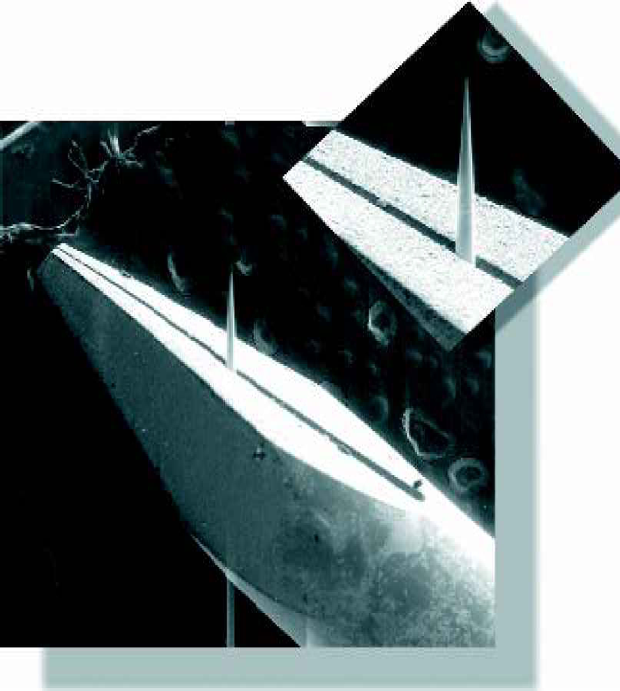
Ground pins obtain grind marks and directional polish lines. Surface contaminants, including grease, dirt, and iron, are inherent to the metal fabrication process. Mechanical cutting and polishing will leave abrasives and iron particles embedded in the metal. Mechanical fabrication can create local galvanic differences. Both contaminates and residual stresses within the cold worked surface layer may produce localized galvanic corrosion cells. These deformities increase corrosion and carryover, thus decreasing the effectiveness of pin cleansing and reproducibility of array printing (Figure 1).
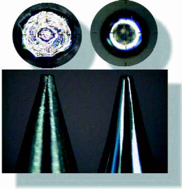
Ground vs. ECP tips 450x.
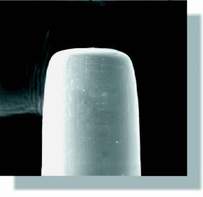
200μ diameter polished tip. 2,000x SEM.
Results
Highly Polished — Microfinish
The properties (surface tension, viscosity) of the spotting substrate surface, pin surface, and the sample fluid determine the amount of fluid to be deposited and how much the sample will spread once deposited. Improved microfinishes can do more than improve the appearance of a part. Because electropolishing is not a surface coating, there is no risk of the surface distorting or peeling over time. Electropolishing can also produce surface texturing, which is uniform and creates increased surface tension and surface area.
The most striking benefit of electropolishing is the reflective physical appearance. Superior microfinishes: lower friction, reduce real surface area, allow for easier sanitation, and improve heat and light reflection. Our electropolishing process can produce microfinish values of 1Ra. Thus, a highly reflective surface decreases surface tension and acts as a hydrophobic surface. Electropolishing can create surface finishes with RMS values from 1–4. Decreased surface tension creates a focused spot symmetry, uniformity and lowered CVs (Figure 2).
Zonal Texturing & Coating
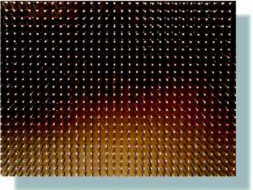
Through a proprietary process, spotting pins can be treated to produce a zonal microscopically textured surface. Texturing creates new surfaces, increasing the surface area and surface tension. The surface energy decreases inversely with the amount of texturing. Zonal texturing is used to increase spot density and spot size without increasing pin sizes. This is very effective with lower viscosity spotting solutions. This also allows for smaller diameter spotting pins to increase spotting volume, thus higher density microarrays are possible (Figure 3).
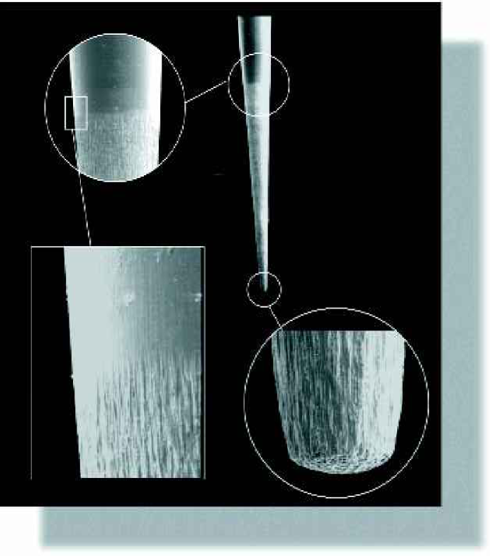
Zonal texturing. SEMs various magnifications.
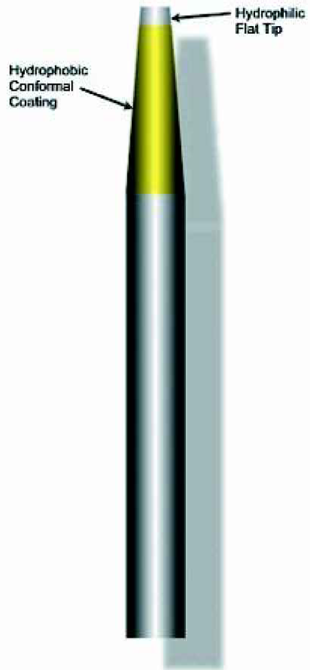
Point Technologies employs a biocompatible, dipped polyimide coating to selectively create decreased surface tensions for a variety of fluid viscosities. This minimizes the quantity of spotting solution dispensed, while controlling the spot size and morphology. The polyimide coating also allows for easier cleaning of the pins (Figure 4).
Passivation & Cleaning
Passivation occurs with electropolishing. Passivation creates the formation of a thick (greater than 20 angstroms), uniform and protective passive oxide layer. This layer increases the metal's corrosion resistance. The improved corrosion resistance is quantifiable and reproducible. The presence of exogenous surface contamination may disrupt the formation of metal's naturally corrosion resistant surface layer. Electropolishing removes surface material and surface contaminates, thus minimizing the possibility of local corrosion cells and leaves the surface with an even electrode potential.
The electropolished surface is easily cleaned due to the absence of mechanical grind marks and pitting which is common with current spotting pins. By removing burrs, occlusions, and other metal working marks, the surface is easier to clean and will not retain contaminants. Tests have shown that microbiological contamination of an electropolished surface is miniscule when compared to an untreated surface. The bugs quite simply have no place to hide on a smooth surface. The inherent benefits derived from electropolishing are that surface leveling reduces the total surface height and relieves much of the surface tension inherent in mechanical polishing, and it enhances the optimization of cleanability and sterilization of machined metals. 4
Print Heads
The print head is the core of the system, being the device that transfers the sample fluid from the microtitre plate to the printing substrate. Point Technologies has developed customized print head assemblies with advanced designs, which provide controlled contact force, high throughput, tight tolerances for planarity and alignment, and high-density arrays.
For pin-based dispensing, the pins are held such that they move freely up and down in the print head during contact with the printing substrate surface to compensate for planarity tolerances found in the stages and slides. Enhanced print head and pin design compensates for tolerances in planarity, while regulating the contact force and contact time. This design improvement provides a significant increase in the accuracy of the assay data. Tight tolerances for print heads and pin diameters allow for low pin vibration and increased accuracy in uniformity and spot reproducibility. 6
Print head assemblies have interchangeable mounting brackets for increased ease of start-up. Microarraying instrumentation from a variety of different manufacturers can be utilized. In addition, different kinds of pins may be preferred for special applications. It is therefore rational to have a microarrayer with interchangeable microarraying heads; such that both solid pins and split pins can be used. Typically, the spacing of the pins in the print head is much larger than the spacing of spots on the microarray. The spots routinely do not directly map from the source plate to the array. Most microtiter plates contain 96, 384 or 1536 wells, the center-to-center spacings are 9.0, 4.5 and 2.25mm, respectively. Point Technologies has the ability to produce custom microtiter source plates to match any high-density array.
High Throughput
The ability to set-up unattended long runs makes it possible to fully capitalize on the labor saving potential of robotic systems. Using Point Technologies' micromachining technology, high-density arrays are possible. High-density microarrays provide for high throughput due to the number of spots printed with each touchdown. Spotting pins can be manufactured as small as 25μm diameter shafts with sub-micron points, truncated tips, conical tips, and other advanced tip designs (Figure 5). Pin diameters and tip shapes are customized to produce a calculated spot shape and size using the least amount of spotting fluid (Figure 6). Smaller diameter spotting pins create the possibility of high-density microarrays with pin densities of 1536 and greater (Figure 7). Customized, zero-tolerance matched-pin assemblies allow for spotting a wide variety of genomic and proteomic fluids. Pin matching allows for greater uniformity of spot-to-spot and pin-to-pin sample deposition. Cleaning time and risk of carryover is also reduced significantly due to microfinishes and passivation techniques. High throughput equals increased cost savings and reliability.
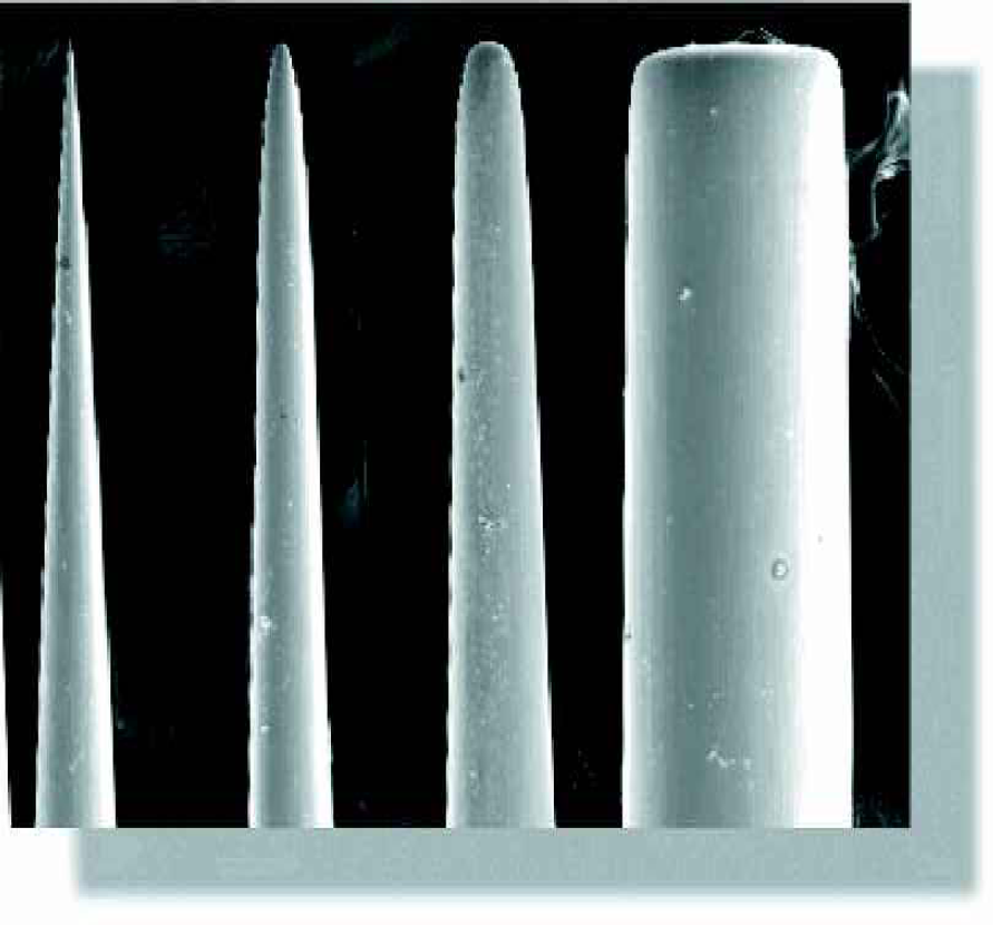
Tip styles.
50μm, 100μm, 150μm, 200μm tip diameters. SEM 80x
Conclusion
The microarraying world is changing at an accelerating rate. High throughput and the robustness of the microarraying instrumentation have led to new discoveries. The next frontier of proteomics is demanding microarrayers to spot higher viscosity solutions onto a variety of dissimilar spotting substrates. Current spotting pins have a multitude of problems such as: poor spot reproducibility, poor uniformity, decreased throughput and pin clogging.
Point Technologies is changing the way microarray spotting is being performed. Instead of using a “one-pin-fits-all” attitude, we customize the pins and print heads to meet your application demands. Thus, the “Spotting Accelerator™” has been developed. The spotting accelerator is a high density, high throughput print head assembly which uses a unique pin design produced to fit your application requirements. Emphasis has been placed on producing the “perfect spots” customized to each microarraying application. Uniform surface texturing such as highly polished or matte finishes, and hydrophilic/hydrophobic zonal coating is produced using Point Technologies' proprietary micro-machining technology. Micro-fabrication also permits the production of advanced pin designs, and high density, high throughput print-head assemblies of 1536 pins and greater. Point Technologies specializes in the micro-electrochemical machining of spotting pins in any size, shape and configuration (Figure 8).
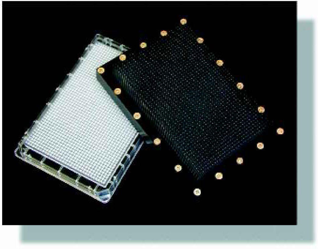
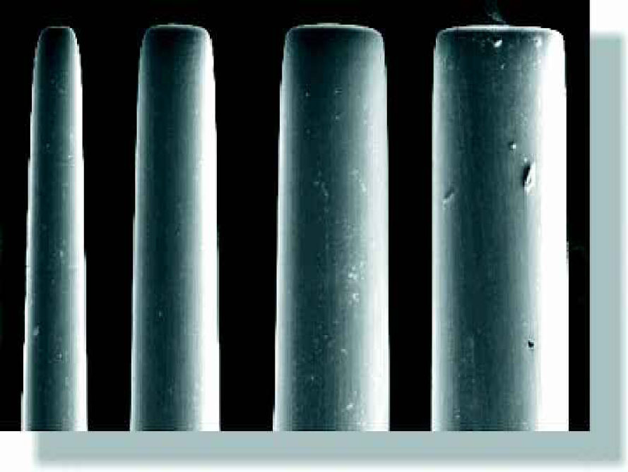
1,536 array shown with well plate.
75μm Solid Pin through Slotted Pin. SEM 20x and 100x.