
Abstract
This research uses the geometry matching technique to identify the different objects. The object is extracted from the background. The second moment 6 is used to find the orientation and the center point of the extracted object. Since the second moment can find the orientations and the center point of the object, the perfect object and the test object can be aligned to the same orientation. Furthermore, these two images can be shifted to the same centroid. After this, the perfect object can be subtracted from the test face. By using the subtracted result, the objects can be classified. The techniques used in this research can very accurately classify different objects.
SECTION 1: INTRODUCTION
This paper investigates the use of object shifting, object rotating, and object subtracting techniques to differentiate objects. When an object image is taken, many useful geometry features might be contained in this image. In the image, since the background and the object are different, based on this difference, the threshold is set to extract the object image. The following techniques — Sobel operator, edge searching and thinning, noise removing, and feature-extracting algorithms are applied to extract the shape and find the position of the object. In this research, geometric and feature-based matching are the principles used to recognize different objects.
Currently, the only efficient way to recognize different objects is by human being brain. Now, researchers are trying to develop new technology to recognize objects by machine. Past work in this area has used several different kinds of strategies to identify objects. They are neural network 4,15 , elastic frame matching 11,15 , isodensity line 12 , template matching 3,9,15 , geometric and feature-based matching 3,10,12 , profile description 1 , volumetric frequency representation 2 , biometrics 6 , optimal separating hyperplace 13 , Gabor wavelets 14 , coding representation 11 , and optical network. However, some of them need a lot of computation time 9,12 ; some are very sensitive to the noise 9 ; some have very complicated mathematical models 12,15 and some have very complicated neural training algorithms 4,12,15 . Here, we propose a different approach, which combines several techniques to cope with the object shifting and rotating problems. Thus, the algorithms developed here can automatically extract the objects and identify an object without involving further human effort.
In this research, the object to be identified is a human face, a complex image composed of several smaller objects. The differences in the shapes, sizes, and orientations of these objects are used to recognize the images. The distances between the objects within a given image are also used to classify different images. In this research, two-dimensional images are processed; three-dimensional images are not investigated.
The major axis and centroid algorithms are used to find the orientations and locations of the feature objects. In this research, the centroid and major axis algorithms can very precisely locate the centroids and orientations of the objects. The subtracted results of the gray scale and binary images have the best results to classify different objects. Under normal circumstances, even though the object's position is two-dimensional shifted, two-dimensional rotated, or the scale is slightly changed, the algorithm will still correctly classify different objects.
This paper consists of five sections. Section 2 discusses how to extract the objects. Section 3 explains how to find the centroid and orientation of an object. Section 4 performs the image subtraction. Section 5 concludes the paper.
SECTION 2: OBJECT EXTRACTION
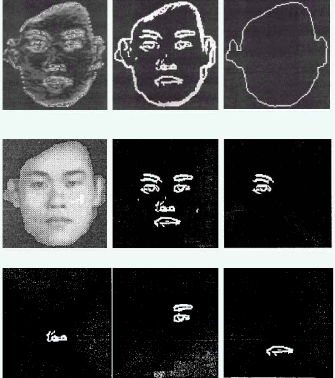
In order to find the locations and orientations of the objects, the objects must be extracted separately. Several image filters are used to remove the image's noises. By the threshold techniques, the useful objects are kept in the image. Applying the contrast-change-detecting algorithm to the threshold image, the object contour can be obtained. By using these contours and by passing an object-extracting window over the original images, the following images can be obtained:
The extracted image
SECTION 3: FINDING THE CENTROID AND ORIENTATION OF AN OBJECT
Finding the centroid
The size of the image used in this research is 128*128 image array. The centroid (ic , jc ) of an image can be found by the following equations:
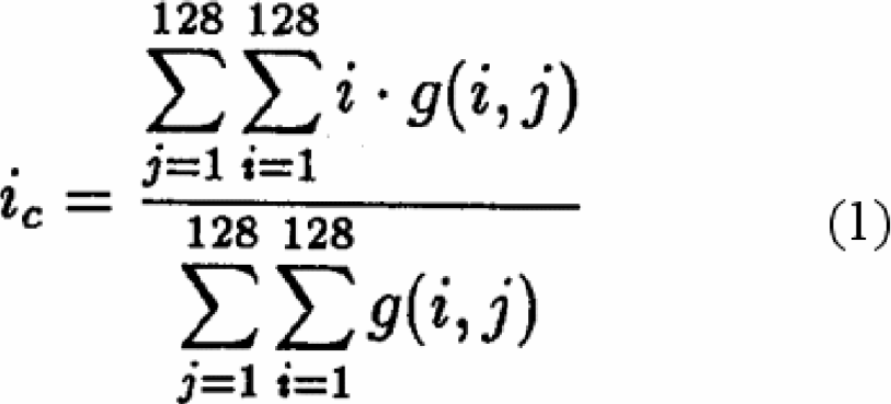
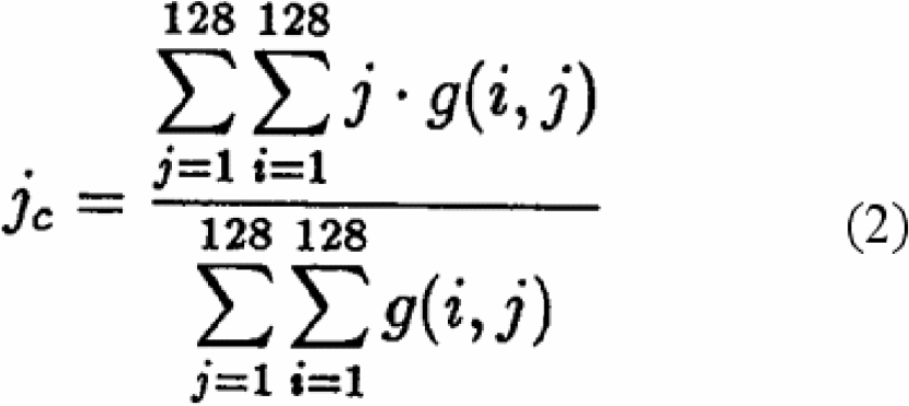
Where g(i,j) is the gray level of the pixel at the location (i,j).
The major axis is the axis around which the object will have the minimum moment of inertia. This is useful in determining the object's orientation. The following graph shows the object major axes:
The object major axis.
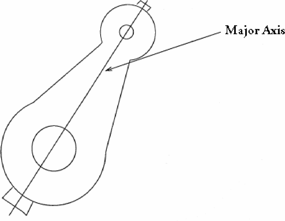
Figure 1 shows the relative position of the major axis. The major axis and X-axis generate an angleØ. The shortest distance from the origin to the major axis is t. The major axis and X-axis intersect at the point (-t/sinØ, 0). The major axis and Y axis intersect at the point (0, t/cosØ). The point inside the major axis which has the minimum distance to the origin is (-t*sinØ, t*cosØ).
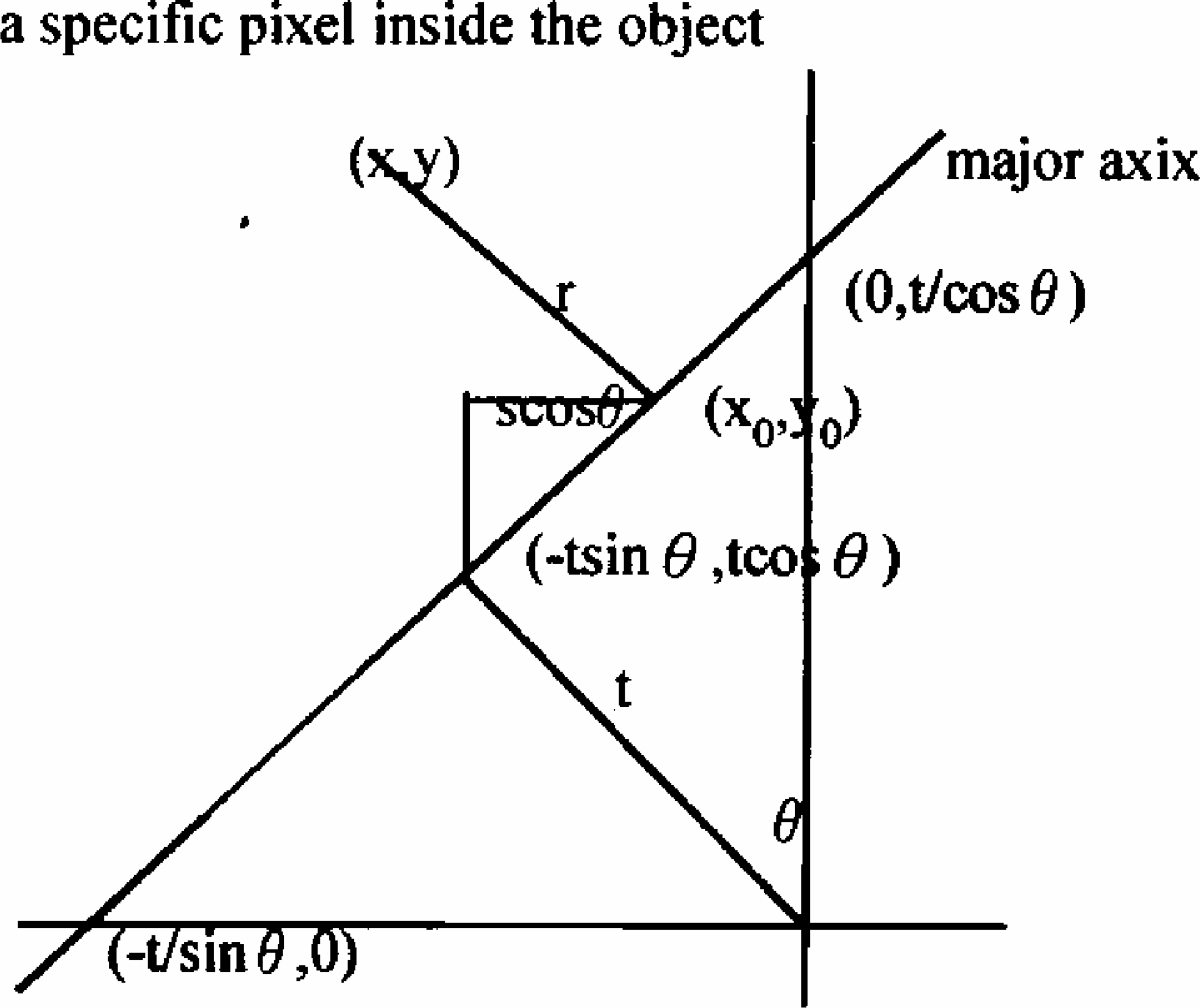
The relative position of the major axis.
By analyzing Figure 1, the equation for the major axis can be expressed as:

In Figure 1, suppose one specific point (x0, y0) is located inside the major axis. From point (x0, y0) to point (-t*sinØ, t*cosØ), the distance is s. From Figure 1, one can find:


Given a point (x,y) on the object, r is the shortest distance between (x, y) and (x0, y0). Clearly,

Equation (4) and (5) are substituted into equation (6). The obtained result is differentiated with respect to s. Setting the result equal to zero, the following equation can be obtained.


The second moment, which describes the object, is:

r is the distance of one specific pixel inside the object to the major axis. However, the distance is the minimum. b(x,y) is the gray level of pixel at location (x,y).
By analyzing equation (1), (2), and (9), the following equations can be derived:

Differentiate with respect to £ c and set the differentiating result to 0, the following equation can be obtained:

The values of a, b, c, and Ø can be found for any images. The Ø will represent the angle of the major axis with respect to the x axis. Based onØ, the algorithm can find the orientation of the object.
SECTION 4: IMAGE SUBTRACTION
Image shifting and rotating
From the above discussion, the orientation of each object can be found. In this research, the object, which needs to be identified, is called the “test image.” In the image database, there are 12 “known images”, one of which matches the “test image.” By overlapping and subtracting each “known image” with the “test image,” the “test image” can be identified.
Figure 2 shows the corresponding position after the test image is rotated Ø degrees toward the known image. (i,j) is the location of one specific point which is located inside the test image. The point in position (i,j) after being rotated Ø degrees will move to the point on the position (i', j'). Clearly, from Figure 2, one can find i=rsinΩ, j=rcosΩ, i'=rsin(Ø+Ω), and j'=rcos(Ø+Ω). Since
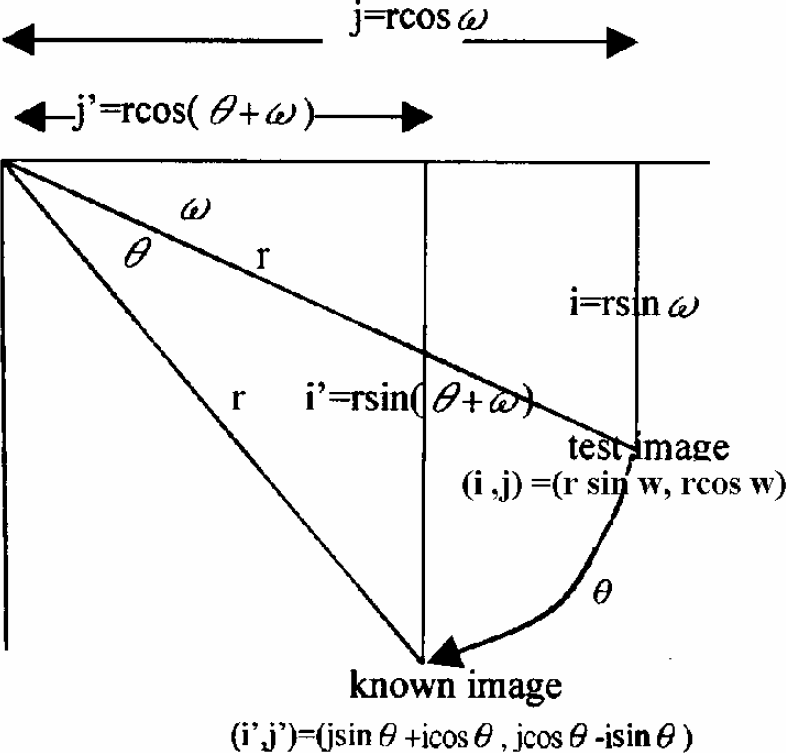
Showing the corresponding position after the test image is rotated θ degrees toward the known image.
sin(Ø+Ω) = sinØcosΩ + cosØsinΩ
and cos(Ø+Ω)=cosØcosΩ-sinØsinΩ,
i'=jsinØ+icosØand j'=jcosØ-isinØ can be obtained. If the rotated direction is clockwise, thenØis positive; otherwise, Øis negative.
By analyzing Figure 2, equation 12 can be obtained.
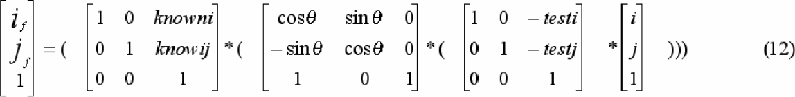
This means that the test image is translated so that the centroid is moved to the origin of the coordinate. Next the picture is rotated so that the test image is at the same orientation as the known image. Finally the picture is translated so that the test image centroid and known image centroid are overlapping. The results of carrying out these operations are shown in equation 13.
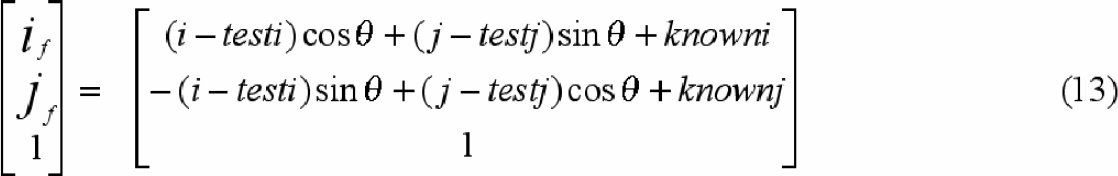
Equation 13 will combine the image rotation and image translation in one step. By using equation 13, one can rotate and transfer the test image point (i, j) to its proper position. (if, jf) thus represents the position in the known image that corresponds to the position (i, j) in the test image.
IMAGE INTERPOLATING
In this research, there are two kinds of image movement: image translation and image rotation. Simply shifting the pixels inside the test image so that the centroid of the test image is overlapping the origin of the coordinate does image translation. After performing image translation, the location of pixels in the test image may have non-integer values. After performing image rotation, the new position of a pixel might not be represented by integers, either. To directly compare pixels from the test image to pixels from the known image, it is necessary to find values for pixels in the test image at the same points (integer values) as those in the known image.
The non-integer coordinate positions, which are obtained from the calculation of the mathematical function 13, have different distances to their four neighboring integer pixels. The gray level of these non-integer points need to be interpolated from their four neighboring integer pixels in order to obtain their proper gray level values.
Image subtraction
After the image interpolation, the known and test images lie in the integer points. Both images have the same orientation. The centroids of both images are overlapped. Image subtraction can now be applied to both images.
SECTION 5: RESULTS AND CONCLUSIONS
Photos of 12 different people (images 01,02… 12) are used in this research; these 12 different people are called the known image. With the goal being the identification of image 01, image 01 is the test image. The gray scale image subtraction is shown in Figure 3. The binary image subtraction is shown in Figure 4.
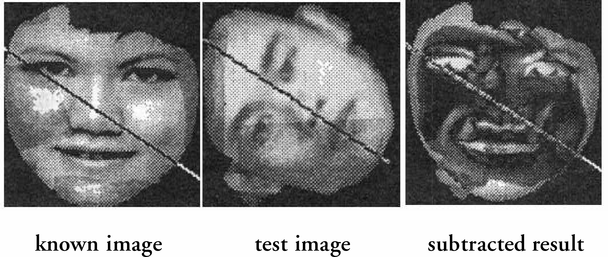
The gray scale image subtraction.

The binary image subtraction.
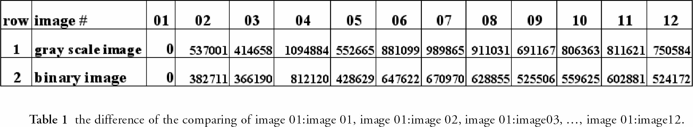
The result of the subtraction of each image with image 01, respectively, is shown in Table 1. The second row of table 1 shows the gray scale image subtracted result. The third row of table 1 shows the binary image subtracted result.
the difference of the comparing of image 01:image 01, image 01:image 02, image 01:image03, …, image 01:image12.
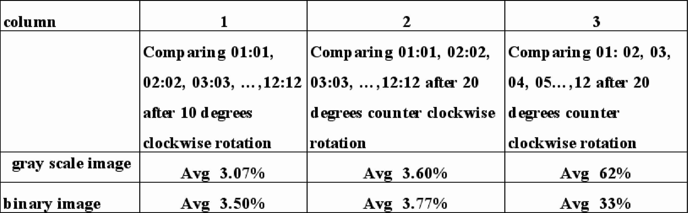
The quality of the techniques used in this research is tested in a two-step process. First, stationary, 10 degrees clockwise, and 20 degrees counter-clockwise rotation photos are taken for each object. The image translation, rotation, and subtraction are applied to the original (stationary) and its two rotated images, respectively. In other words, the difference of the comparing of image 01:image 01, image 02:image 02, image 03:image 03, —-, image 12:image 12 is found to its two rotated images. The sums of the gray levels of the subtracted results can be obtained. These values are divided by the sums of the gray levels of the original (stationary) images. The percentages are shown in the second and third columns of Table 2.
Second, the stationary image of image 01 is successively subtracted from the 20 degrees counter-clockwise images of the other 11 objects. In other words, the difference of the comparing of image 01:image 02, image 01:image 03, image 01:image04, —-, image 01:image 12 is found between the stationary image of image 01 and the 20° counter-clockwise rotation image of the other images. The sums of the gray levels of the subtracted results are divided by the sum of the gray levels of object 01. The percentages are shown in the fourth column in Table 2. From table 1 and
Footnotes
Acknowledgements
If you are interested in seeing more articles like this in JALA, please email