
Abstract
Liquid handling systems are in common use throughout the research chemistry industry, for a variety of fluid dispensing applications. However, few manual or automatic systems have been specifically designed for dosing highly corrosive acid/solvent mixes. Even fewer can withstand 60% Trifluoroacetic acid mixes — a standard mixture for cleavage of compound from polystyrene beads. A design is presented of such an automated dosing system. The requirements are to reduce human exposure to chemicals, remove potential for repetitive strain injury, and increase reaction plate throughput. Material choice, the use of process valves, equipment protection, and a novel plate detection system are discussed. Modifications resulting from the prototype test are discussed, along with additional improvements to the system and further research.
INTRODUCTION
A bespoke chemical cleavage dosing system has been successfully implemented at Oxford Asymmetry International, a UK Combinatorial Chemistry company. It forms part of the company's overall objective to embrace new manufacturing technologies and gain by increasing throughput, flexibility, and enhancing employee safety. Solid phase combinatorial chemistry is a process by which compounds are constructed using ‘combinations’ of reagents dosed onto ‘combinations’ of solid supporting resins. Varying the resins and reagents in the row — column format of an array produces libraries of dissimilar compounds. The compounds are built on solid resins to allow physical handling. A filter will hold the resin, but allow reagents and washing solvents to pass through. The final process in combinatorial chemistry is the breaking of the required compound from the solid supporting resin. This is termed chemical cleavage.
Cleavage routinely requires the dosing of a Trifluoroacetic acid (TFA)/Dichloromethane (DCM) liquid mixture. Approximately 75% of compound cleavage is TFA/DCM mediated. The most common mix ratio of TFA/DCM is 60%/40%, respectively, by volume. Current protocols use finger actuated stepper pipettes to dose 0.75 ml into each well of a 48 or 96 deep well fritted micro-lute plate. The compounds and cleaving agent pass through the individual frits (filters) to be collected by a closed bottom 48 or 96 well microtitre collection plate. Cleavage is typically performed four times on each well. Cleaving 96 well plates, in a 24-plate batch requires up to 9216 individual doses. The potential for Repetitive Strain Injury 1 (RSI) in stepper operation has raised corporate Health and Safety issues.
TFA is handled with caution 2 as the acid is extremely corrosive and readily vaporises at ambient conditions. Chemists wear full protective clothing, face shield, and gauntlets. The protective gauntlets hamper operation of the finger-triggered stepper gun, and the face shield impairs vision and head movement. Cleaving takes place in the confined space of a fume-hood with the chemist reaching over the laid-out plates, working in close proximity to hazardous chemicals. Potential environmental and physical demands raise Health and Safety concerns. The dosing stepper gun has not been specifically designed for use with a TFA/DCM mixture. The stepper usually fails after two batches of dosing. The barrel is discarded, and a replacement used, adding to the cost of the process. Commercial automated liquid handling equipment has been trialed, but showed signs of severe corrosion caused by acid vapour attack.
The requirement was to design dosing equipment to meet the following objectives:
Remove potential for RSI.
Significantly limit exposure to chemicals.
Long product life — function in a TFA/DCM liquid and vapour environment.
Dose 0.75 ml ± 10%.
Fit in a fumehood 600mm by 1000mm.
Additionally:
Operate by technicians, not chemists.
Increase plate throughput.
RSI prevention and limiting exposure of operators to chemicals requires an automated solution.
METHOD
Materials
The specification of metals and plastics requires consideration of stability in a TFA/DCM liquid/vapour environment. Laboratory chemists provided information on materials resistant to both chemicals:
Plastics
Polytetrafluoroethylene (PTFE/Teflon)
Polypropylene
Polyethylene
Fluorinated Ethylene Polymer FEP
Perfluoroalkoxy PFA
Metals
Stainless steel 316L
Aluminium
Titanium
Nickel
Polypropylene was selected for ‘damp’ components due to resistance to TFA/DCM, cost, availability, and strength. The ‘wet’ components such as valves and tubes were specified as PTFE, which although more expensive has the required inert properties. Supporting structures used stronger anodised aluminium.
Design
There are fundamentally two ways of dosing TFA/DCM into the wells:
a) Move the dosing head.
Indexing the dosing head requires a support and motion structure situated above acid vapours emanating from the plate and head — the flow of fumehood air is upwards. Adequately protecting motion systems for the lifetime of the equipment would be difficult to achieve. Acid/solvent vapour would soon penetrate and degrade bearings, seals, and mechanical linkages.
b) Move the plate.
Indexing the plates allows the plate carrier to partially shield actuation systems from direct contact with liquid or vapour, and allow a static TFA-proof structure for dispense head mounting. This design strategy was chosen.
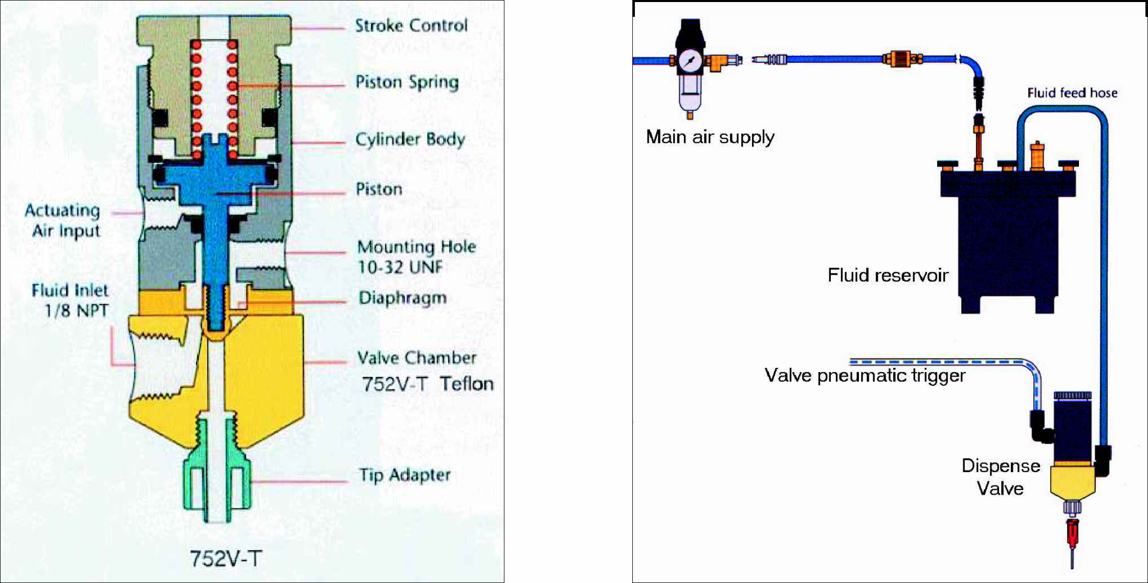
A ‘measured volume’ dosing head (syringe type), was discounted due to the need for a loading bath and consequent copious acid vapour fumes. Additionally, swelling or degradation of the syringe seals and barrels by either DCM or TFA would limit the lifetime of the dedicated equipment. Syringe actuation systems would also need to be TFA proof — and complicate design considerably. A switched EFD (Dunstable, UK), 752V-T valve (Figure 1), with PTFE wetted parts was considered more appropriate. Dispense volume is controlled by the duration of the ‘on’ signal.
TFA/DCM is supplied to the valves under low pressure (0.75 bar), in an enclosed system. Vapour exists only on dispense, and supply tank refill (Figure 2).
Performance
The design criteria calls for an increase in plate throughput. The rate of manual dosing was timed at an average of 33 minutes to dose 24 plates of 96 wells, with one aliquot of TFA/DCM. In order to maximise efficiency, the automated equipment required batch operation. The physical size of the fumehood restricts the carrier to a maximum plate array of 8, taking into consideration space required for storing plates ready for use, unloading dosed plates, and locating the storage tank. Given that each plate has a dedicated dosing valve (discussed later), and that load/unload times are similar for both manual and automatic systems. Parallel operation with an estimated dosing time of 4 minutes per eight plates allows for 24 plates to be dosed one aliquot in 12 minutes. Estimated increase in performance is nearly three times that of manual dosing.
Flexibility
In choosing an 8 bay system, consideration was given to allow flexible capacity — the chemists do not want to wait for plates to make up an equipment batch of eight. So each plate requires its own dispense valve. Automatic plate-location detection is needed to maintain simple operation. The alternative is operator entry via a terminal, and the consequent possibility of human error causing cleaving agent to be dispensed into a vacant bay. The clean up would involve a hazardous task, and take time to perform.
The plate detection system incorporates an SMC Pneumatics Air Catch Sensor (Milton Keynes, UK), to monitor each bay. The plate carrier has an air bleed orifice machined into the side-wall of each of the eight recessed bays. Bleed air is supplied by the eight air catch sensors. Plate presence is detected by registering the pressure increase of restricted airflow caused by the plate blocking the orifice. The air catch sensor requires accurate placing of the plate. A plate tilt would allow increased airflow on one side of the orifice, failing to trip the sensor (Figure 3).
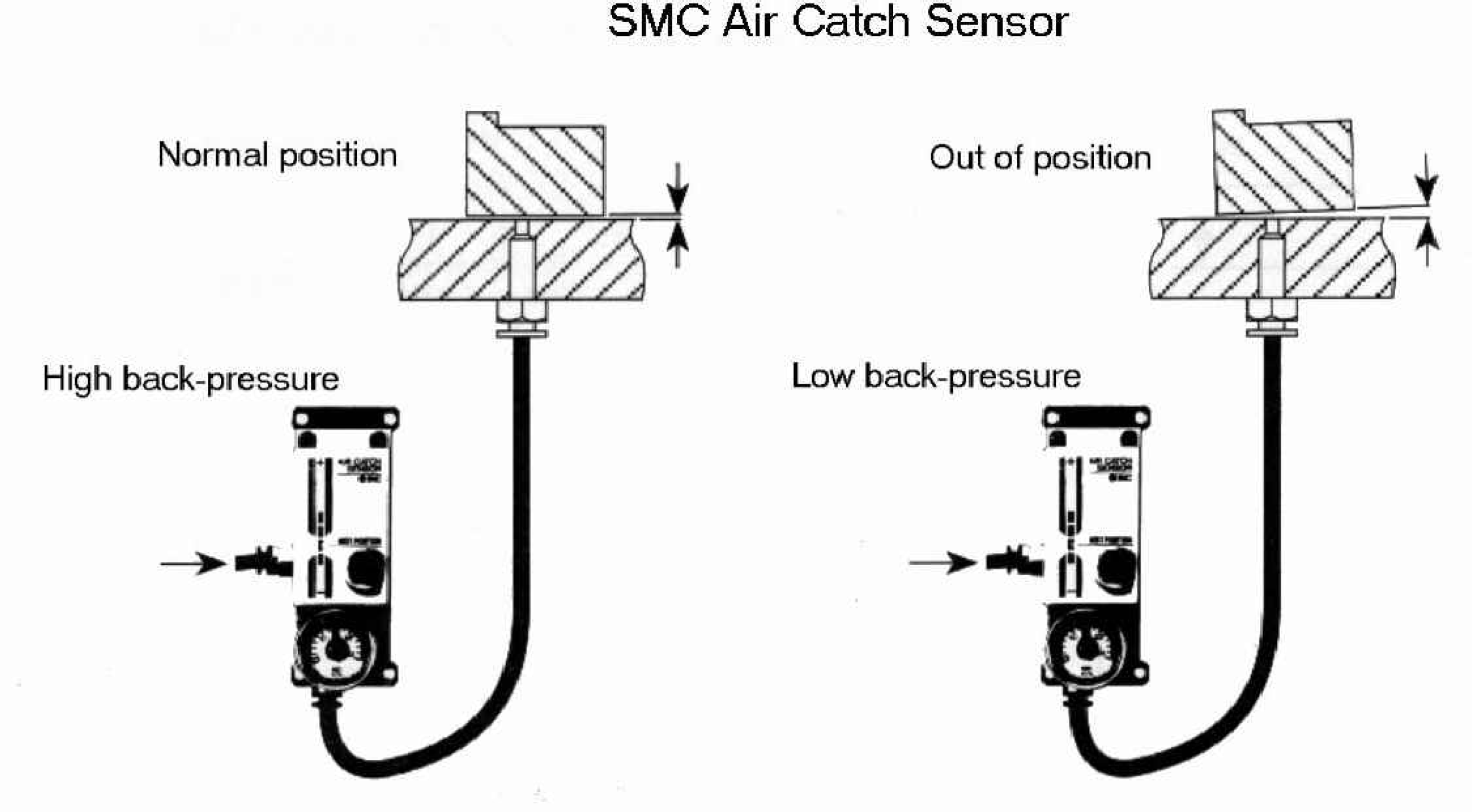
Schematic of an air-catch sensor. Actual system is applied horizontally.
A ‘push-fit’ design of the recessed bay was incorporated to both maximise this effect and to allow for the manufacturing tolerances of plate moulding. The advantages over other systems are:
Sensor duplication is not required to ensure the plate is accurately located.
This system is self-purging — performance in a TFA/DCM environment is assured.
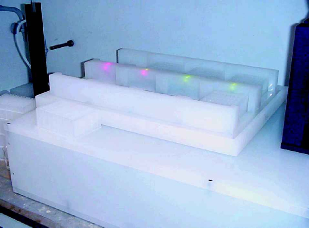
Plate sensor status is mimicked to the operator by dual state Light Emitting Diodes (LED), built into the central locator of the plate carrier (Figure 4). The LEDs are mounted in blind holes, bored to 3mm below the top surface of the central locator. The translucent property of polypropylene allows good visibility of light through the 3mm skin. LED location next to each bay gives a unique check for correct sensor operation, and the system provides immediate feedback to confirm good plate placement in the operators line-of-sight, so minimising head movement.
LEDs in central locator.
Box design
The plate carrier is indexed by an X-Y table enclosed in a polypropylene box. Mounted to the X-Y table, a hollow pillar passes through an aperture in the box top and mechanically couples to the plate carrier (Figure 5).
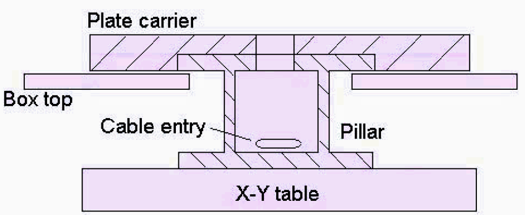
Construction schematic.
The box is fed with low-pressure air to maintain a purged environment. By adjusting the shimming of the pillar, the gap between the plate carrier and box lid can be minimised to reduce the rate of purge air required to prevent vapour ingress. The hollow pillar provides a vapour-screened path for all electric and pneumatic signals. LED wires and pneumatic tubes run up the pillar to the base of the plate carrier, through an access tunnel, and are then distributed to each bay by a hollow ‘central locator’ block sealed onto the plate-carrier top surface. This central locator block, in conjunction with a pair of side locator blocks, ensures that the top microlute plates sit correctly on the accurately located microtitre plates.
The valve gantry is manufactured from anodised aluminium. A hinged arm supports four cross beams. Each end of the cross beams locates one dispense valve. The mounting pitch is set to locate the valve dispense head over well position ‘A1’ of each plate with the plate carrier in the ‘home’ position. The hinge assembly and end stop are both mounted on the polypropylene box. The end stop incorporates an air catch sensor orifice that is blocked by a correctly lowered arm. The signal from this self-purging sensor provides input to the control system's safety check. The arm is hinged to allow the operator to load and unload plates without damaging valve heads.
All control cables and pneumatic tubes from the polypropylene box to the externally mounted control panel are shrouded by a 50mm-diameter polypropylene pipe.
The 5 litre TFA/DCM pressure tank is located inside the fume-hood. The tank incorporates a protective polypropylene liner, and float-type liquid level detector to ensure sufficient fluid for operation. Pressure is applied via a pneumatic valve located in the control cabinet. A check valve prevents TFA vapour flowing back into the control cabinet. Tank pressure is exhausted by a pneumatically signalled EFD valve located on the tank.
Control & Operator Safety
The control panel houses an Allen Bradley (Milton Keynes, UK), SLC503 Programmable Logic Controller (PLC), which performs all sequencing tasks. Operators control the system through three pushbuttons. ‘Home’ moves the X-Y table to dispense position ‘A1’. ‘Arm’ applies pressure to the TFA storage tank once all the hardwired safety systems and controller preconditions have been met as follows:
TFA storage tank level switch must be tripped to indicate sufficient volume available.
Two fumehood safety switches must be ‘made’ by closure of the sash — preventing operator exposure to pressurised TFA/DCM in the event of a malfunction.
Emergency stop button not latched.
Air supply monitoring switch must indicate pressure above set level.
X-Y table must be in ‘home’ position — ready to dose.
‘Start’ commences dispense sequence once the system has been armed. The emergency stop and two fumehood sash safety switches are hard-wired to a relay that disconnects the power supply to the control system. The emergency stop button, or lifting the sash, automatically stops X-Y movement and dumps pressure from the TFA tank as well as preventing actuation of the dispense valves. The system is designed such that it will fail safe in the event of a power or air supply failure. A 3-light indicator stack is mounted on the cabinet. Indicators are running, ready-to-run, and error.
TESTS
The valve settings and PLC timer were roughly configured using water as a test fluid. The system was checked for leaks. Once a close setting was achieved, the system was flushed with DCM, and then a trial ran on TFA/DCM. Fluid dispense repeatability was improved by rotating valve bodies on their mounting so that the fluid inlet connection would be uppermost when the operator raised the valve gantry. Air or vapour trapped in the valve manifolds could then enter the main ring supply to be bled off. Setting dosing volume had been hampered by these traps. Fluid distribution was altered from a spur to a ring supply to provide free fluid flow to all valves. It had been observed that the end-of-line valves dispensed slightly lower volumes when all eight valves were triggered when compared to an individual triggering.
The PLC ‘on’ signal duration was programmed for 600 milliseconds. The supply tank pressure was set to 0.75 bar. Each valve was then set by adjusting the stroke control (Figure 1), to dispense an aliquot of 0.75ml ± 10%. The wide tolerance allowed by the design specification is consistently achievable.
The time taken to dose 96 wells is 3 minutes 49 seconds. This is an improvement on the design stage estimation of four minutes.
CONCLUSION
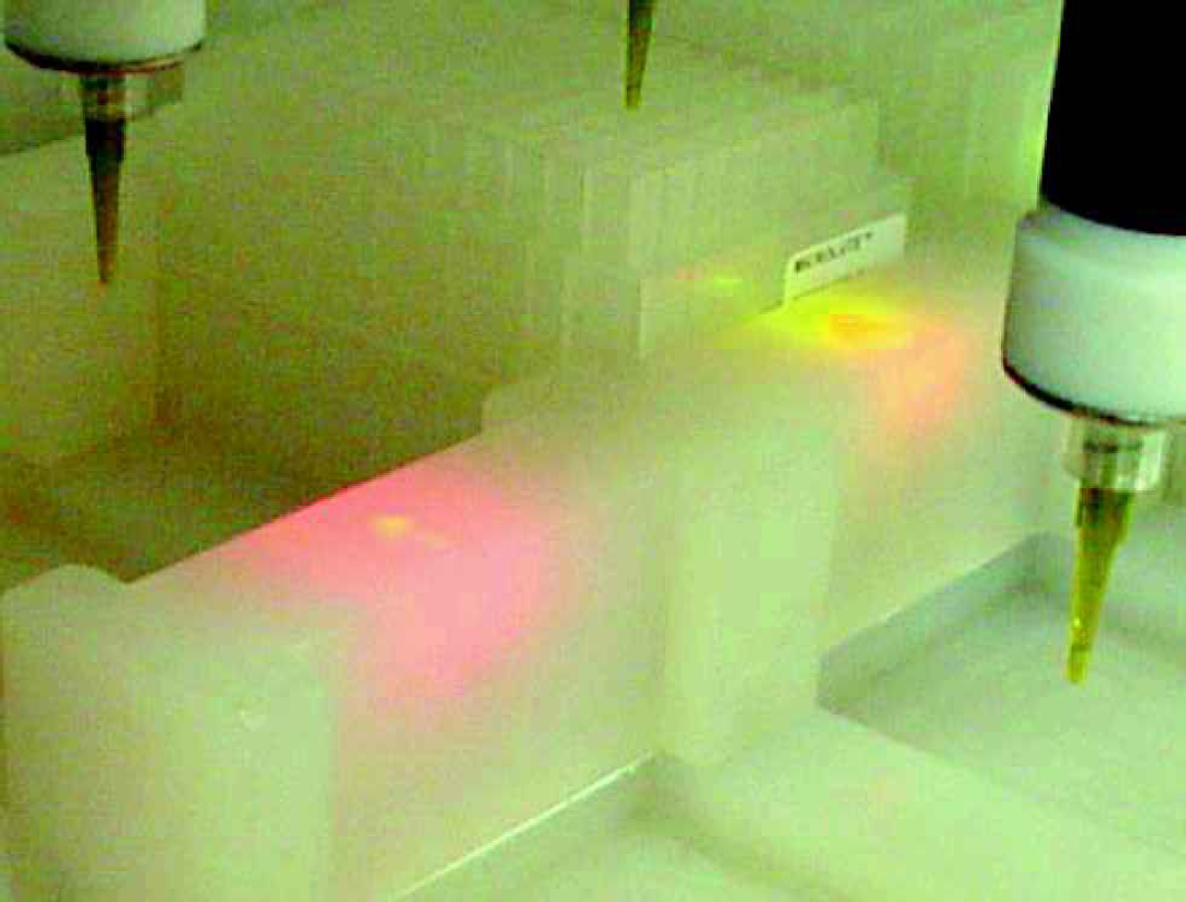
The prototype is now in full production use (Fig 6 & 7). The system will be monitored for aliquot drift, and material degradation.
The design requirements have been met as follows:
Removal of RSI.
Chemical exposure limited to unload and tank refill. The operator does not have prolonged contact.
Longer product life. The equipment has been designed specifically for operation in a TFA/DCM environment.
The required dose of 0.75 ml ± 10% is consistently achievable.
The system is installed in a fumehood measuring 600mm by 1000mm.
Operation is simply via three pushbuttons. Data entry by skilled staff is not required.
Nearly three-fold production increase. Automation doses 24 plates in 11 minutes 30 seconds compared to 33 minutes manually.
Dispensing table with gantry raised.
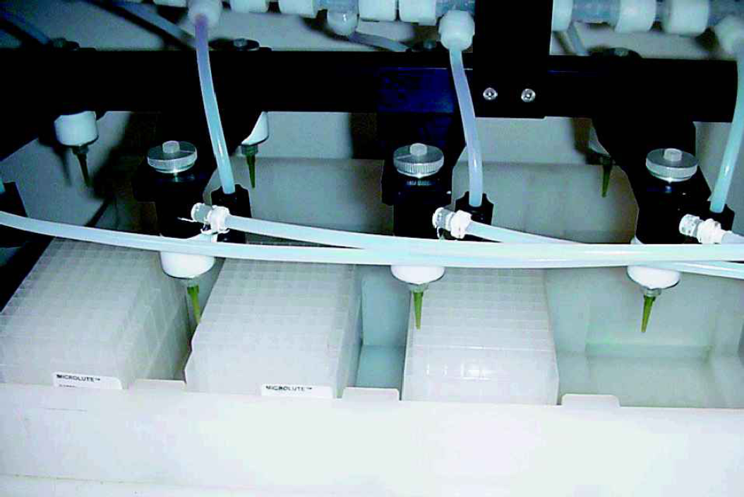
Dispensing table with gantry in position.
DISCUSSION
Additional increases in dosing rate may be achieved by duplicating dispense valves per plate. The physical size of the valves restricts this to a maximum of four per plate, translating into a twelve fold increase over manual dosing.
The X-Y table moves the 96 well plates in a ‘raster’ path. Dosing time could be reduced by following a ‘snake’ path to remove redundant movement. This modification is currently being undertaken.
The system is designed as a standalone piece of equipment. The same technology could be incorporated into a production line or cellular system. Developing robot or automated load/unload systems removes the need for localised plate sensing. So long as a data link exists between load/unload systems and the cleavage PLC, the PLC would be notified which bays are utilised or empty and trigger the corresponding dosing valves. Push-fit bays would also not be required. This would simplify automatic plate handling considerably. A fully integrated system could take advantage of the expansion features of a PLC. A single controller could perform load/dose/unload functions as well as communicate with peer equipment and management systems.
A significant aspect of the design was material choice. Information regarding suitability of material was not readily available in sufficient detail. Further research in this area is required.
ACKNOWLEDGEMENTS
We would like to thank the following people for their inestimable help:
Dr. A. D. Baxter (Oxford Asymmetry International), Dr. R. Marmon (Oxford Asymmetry International), Mr. P. Gorse (Oxford Asymmetry International), Mr. J. Meadows (Warwick Manufacturing Group), Mr. R. McLaughlin (Warwick Manufacturing Group), and Mr. A. Nixon (N & S Precision).
We would also like to acknowledge the Teaching Company Directorate for facilitating the partnership between Oxford Asymmetry International and the University of Warwick.
Footnotes
Acknowledgements
If you are interested in seeing more articles like this in JALA, please email